
You've exported the layout, your team is waiting for boards, and procurement wants permission to place the order. Then the assembler asks about a missing rotation convention, an unavailable regulator, and whether the QFN exposed pad needs a different stencil aperture. None of those questions feels like product development, but your answers determine whether the boards will produce useful engineering evidence or just light up on the bench.
PCB prototype assembly should validate the design and the manufacturing process together. Order a build that lets you explain what happened, reproduce it, and carry the conclusions into production.
Table of Contents
- Why Your Prototype Build Matters More Than You Think
- The Files You Must Send Before Anything Gets Built
- Running the DFM Review Before You Click Submit
- Sourcing Components and Managing Substitution Risk
- Stencils, Paste, and the Reflow Profile That Ties Them Together
- Inspection and Test Layers That Catch What Visual Checks Miss
- Packaging, Shipping, and Reading the Prototype Result
<a id="why-your-prototype-build-matters-more-than-you-think"></a>
Why Your Prototype Build Matters More Than You Think
A board that boots after a technician replaces a component and touches up hidden joints isn't equivalent to a board that passes through the intended assembly process unchanged. Both can support debugging. Only the latter gives you clean evidence about the released design.
This distinction matters whether you're a hardware founder preparing a demonstration, an R&D engineer investigating intermittent behavior, or a procurement lead coordinating suppliers. RF designers need to distinguish circuit performance from build variation. LED and power-electronics teams need thermal measurements tied to known materials, components, and assembly conditions.
<a id="define-the-engineering-question"></a>
Define the engineering question
Before requesting a quote, write down what the build must establish. Separate concept validation from manufacturing validation, and identify any departures from the eventual production configuration.
- Design evidence: Specify the electrical, thermal, RF, and mechanical behaviors you need to evaluate.
- Process evidence: Identify the assembly operations and package types that require verification.
- Acceptance evidence: Agree on workmanship criteria, inspection scope, and the records you'll receive.
- Configuration evidence: Record the released files, installed parts, firmware, and approved deviations.
Shared acceptance language isn't administrative decoration. IPC's role grew from the need for common manufacturing rules, and its bare-board acceptance work established a technical vocabulary that designers, fabricators, and assemblers can use together, as described in this history of IPC standards and electronic manufacturing.
A prototype is useful when you can explain why it passed, not merely demonstrate that it passed.
Assign an engineering owner who can approve deviations without losing control of the baseline. Procurement can coordinate availability, and the assembler can recommend process changes, but neither should redefine what you're validating.
Treat the release package, component approvals, process setup, inspection, and test records as linked evidence. If you don't know which configuration produced a measurement, don't use that measurement to justify production release.
<a id="the-files-you-must-send-before-anything-gets-built"></a>
The Files You Must Send Before Anything Gets Built
Send a controlled release package, not a collection of whichever exports happen to be in your downloads folder. Put the board identifier and revision on the package manifest, drawings, BOM, and test instructions. Ask the assembler to confirm that the package is complete before authorizing fabrication or purchasing.
For fabrication, provide Gerbers with drill and rout data. If you prefer ODB++ or IPC-2581, confirm that the supplier can import your export and agree which dataset controls the build. Don't send conflicting formats and expect the factory to choose correctly.
<a id="prototype-assembly-file-package-at-a-glance"></a>
Prototype Assembly File Package at a Glance
| File Type | Must Contain | Risk When Missing | |---|---|---| | Fabrication data | Copper, solder mask, legend, outline, drill and rout data | Incorrect board interpretation or fabrication hold | | BOM | Manufacturer, exact part number, quantity, reference designators, approved alternates | Purchasing ambiguity or unauthorized substitution | | Pick-and-place file | Reference designator, X/Y coordinates, rotation, board side, units and origin | Placement programming errors | | Stack-up drawing | Layer sequence, materials, copper requirements and impedance instructions | A build that doesn't match electrical assumptions | | Assembly drawing | Polarity, orientation, unpopulated positions and special handling | Incorrect population or technician guesswork | | Test package | Firmware identifier, programming method, test procedure and acceptance limits | Boards shipped without meaningful functional verification |
An internal house-part number isn't enough unless you also provide an unambiguous cross-reference. Include component package information and mark do-not-populate positions consistently across the BOM, placement data, and drawings.
<a id="check-the-exports-against-each-other"></a>
Check the exports against each other
Open the fabrication outputs in a viewer rather than trusting the CAD export command. Then compare the BOM and centroid file against the assembly drawing, especially connectors, polarized capacitors, diodes, and asymmetric packages.
Confirm the assembler's rotation convention and bottom-side interpretation. State the coordinate origin and units explicitly; don't assume the machine programmer will infer them from the outline.
Release discipline: Replace the complete package when a revision changes. Don't scatter corrections across email attachments.
Include a release manifest naming the controlling files and a contact authorized to answer engineering questions. Require written acknowledgment of revised packages so the purchasing team and machine programmer aren't working from different baselines.
<a id="running-the-dfm-review-before-you-click-submit"></a>
Running the DFM Review Before You Click Submit
DFM must evaluate the released design against the factory that will build it. A clean CAD rule check doesn't establish that the selected fabricator, assembly equipment, panel format, and test method can support your requirements.
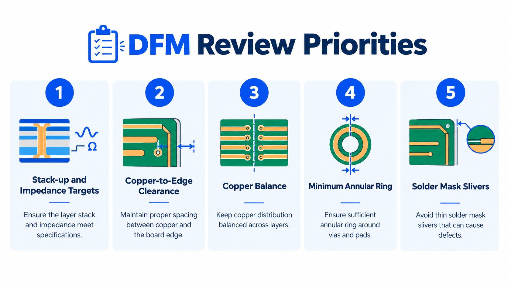
Start with the features that could invalidate the product's engineering assumptions. For controlled-impedance or thermally demanding boards, agree on the stack-up, material choices, copper requirements, and measurement expectations before approving fabrication.
Use these fabrication checks as the starting point, not the entire review.
<a id="review-fabrication-assembly-and-test-separately"></a>
Review fabrication, assembly, and test separately
Ask the fabricator to evaluate copper-to-edge clearance, copper balance, annular rings, drill tolerances, and solder-mask slivers against its actual capabilities. Request explicit approval or proposed changes, not a generic manufacturability statement.
Then compare every critical footprint with the exact selected component package. Pad geometry affects paste deposition, alignment, reflow behavior, and inspectability, which is why land-pattern standardization became central to SMT development, as documented in SMT007's account of surface-mount standards.
- Placement registration: Confirm usable fiducials and clearances around fine-pitch devices.
- Panel handling: Agree on rails, tooling provisions, breakaway locations, and depanelization constraints.
- Test access: Review probe access with the test engineer, including obstruction by tall components.
- Layout corrections: Route unresolved geometry issues through a PCB layout review before releasing the manufacturing files.
<a id="close-findings-with-evidence"></a>
Close findings with evidence
Consider a hypothetical QFN review: the designer checks the perimeter pads, but the assembler questions the exposed-pad stencil pattern. The correct response isn't to add paste until the board works. Compare the component recommendation, copper land, aperture design, and thermal requirements, then approve a documented resolution.
Similarly, a dense BGA fanout needs confirmation against the fabricator's drill and registration capabilities before fabrication starts. Record each finding, its owner, the disposition, and the affected revision.
Don't accept an unresolved DFM issue merely because somebody believes they can fix it during assembly. That turns a design question into an undocumented process experiment.
<a id="sourcing-components-and-managing-substitution-risk"></a>
Sourcing Components and Managing Substitution Risk
Procurement shouldn't approve electrical equivalents on its own. A matching package and headline specification don't establish that an alternate will preserve the behavior you're trying to measure.
Require handling and identification controls even for prototype quantities.
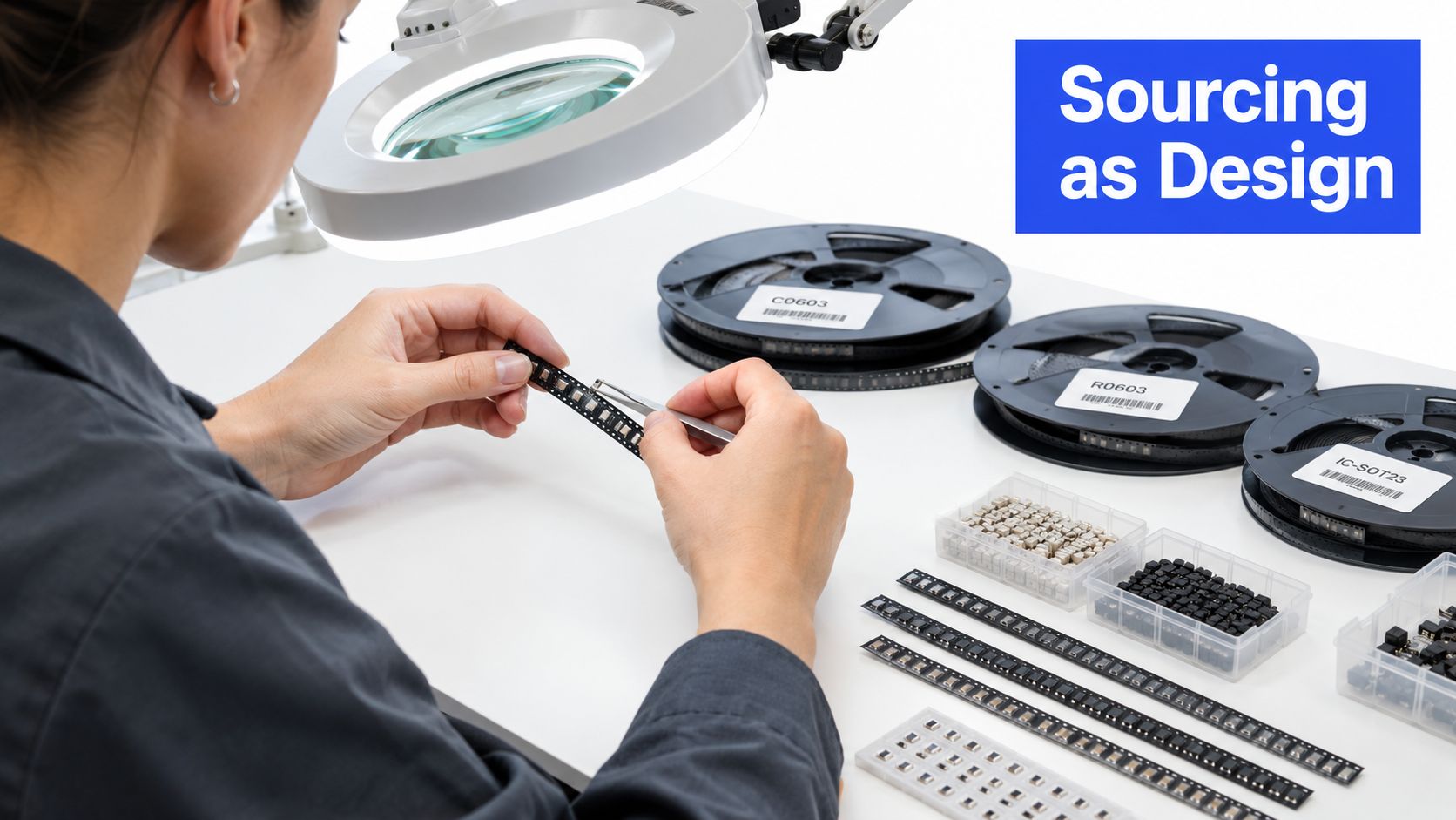
Prefer authorized-distributor sourcing with documented traceability. If an open-market purchase is proposed, require a separate approval covering provenance, incoming verification, and whether the parts are acceptable for the intended validation.
Specify cut-tape, reels, tubes, or trays in consultation with the assembler. Request lot and date-code records for critical devices, and agree on labeling and machine-loading requirements before parts ship.
<a id="classify-alternates-by-validation-risk"></a>
Classify alternates by validation risk
Use this approval framework as an engineering decision, not a purchasing shortcut.
| Risk Class | Candidate Situation | Required Review | |---|---|---| | Low | A noncritical passive with matching relevant characteristics | Check package, rating, tolerance, material characteristics and application requirements | | Medium | A part whose dynamic or thermal behavior matters | Add circuit analysis and targeted electrical or thermal testing | | High | A power-control, RF, programmable or qualification-sensitive device | Require design-owner approval and a documented revalidation plan |
Substitutes can change input capacitance, switching behavior, thermal resistance, coplanarity, RF performance, or qualification status. These risks are part of the sourcing and manufacturability concerns discussed in Duro Labs' PCB DFM guidance.
Review firmware compatibility and regulatory implications explicitly. Mark critical BOM lines no substitution without written customer approval, and identify who can grant that approval.
Use the video as a visual companion, not as authorization to change the BOM.
<iframe width="100%" style="aspect-ratio: 16 / 9;" src="https://www.youtube.com/embed/KtuYqAZXx-8" frameborder="0" allow="autoplay; encrypted-media" allowfullscreen></iframe>A turnkey PCB assembly arrangement can put purchasing and assembly coordination with the supplier. Keep design approval with your engineering team, and record the installed manufacturer part numbers against the build configuration.
A readily available alternate is only useful if its approval preserves the meaning of your test results.
<a id="stencils-paste-and-the-reflow-profile-that-ties-them-together"></a>
Stencils, Paste, and the Reflow Profile That Ties Them Together
Treat solder-paste deposition as the first statistical control point. Don't let the factory treat stencil selection as an automatic accessory purchase while engineering concentrates only on component placement.
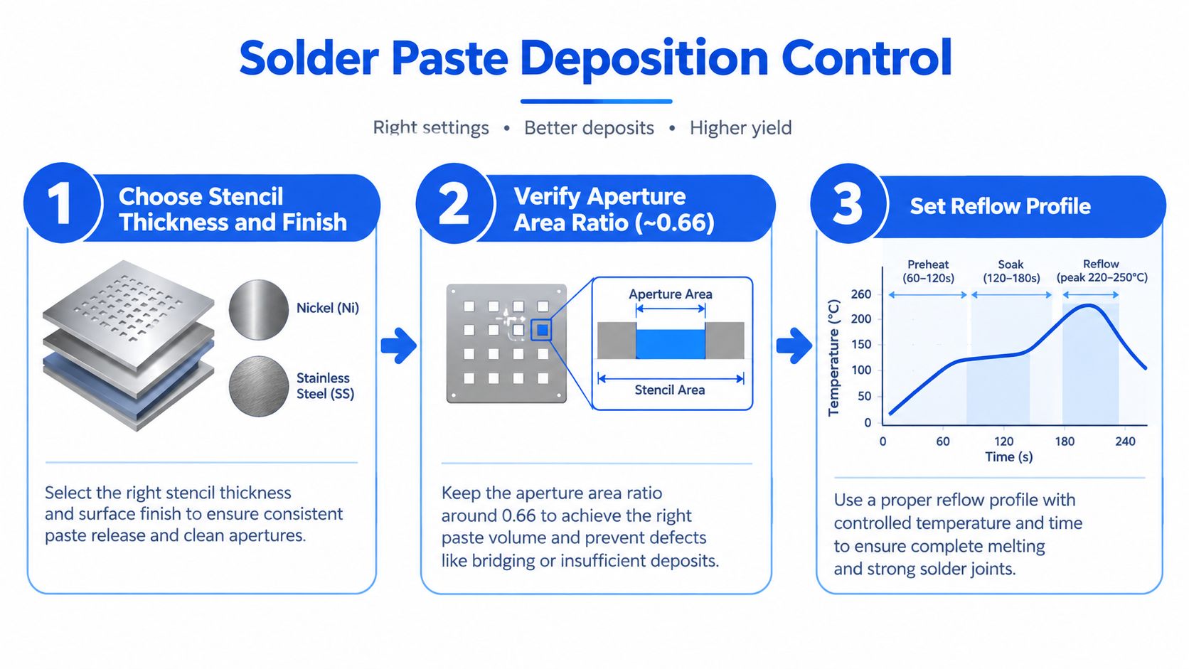
Start by matching the PCB land pattern and stencil design to the component package. Select a laser-cut stainless-steel stencil, then review thickness, aperture geometry, and finish with the process engineer responsible for printing.
<a id="select-the-stencil-around-the-package-mix"></a>
Select the stencil around the package mix
Target an aperture area ratio of at least 0.66 as a baseline, consistent with the SMTA stencil-design guidance for small components. That guidance connects insufficient aperture geometry with reduced paste transfer and insufficient-solder risk, particularly for fine-pitch, QFN, and small-component pads.
Don't confuse area ratio with a universal aperture reduction rule. Ask the engineer to evaluate the aperture opening relative to its wall area and explain how the selected thickness supports the most demanding pads.
For a mixed-package board, require an explicit discussion of competing paste-volume needs. Consider local aperture changes or a stepped stencil where appropriate, but approve the proposal against the package requirements rather than selecting a thicker stencil for the largest connector.
Review SMT stencil options alongside the assembly drawing. Record the approved stencil revision separately from the PCB revision so a later process change remains visible.
Use the flow below to organize the discussion, then verify each stage with measured data.
<a id="control-printing-before-placement"></a>
Control printing before placement
Require paste storage, conditioning, working-life, and stencil-cleaning instructions that follow the selected paste manufacturer's requirements. Record the paste identity and lot, and make first-article print approval part of the build traveler.
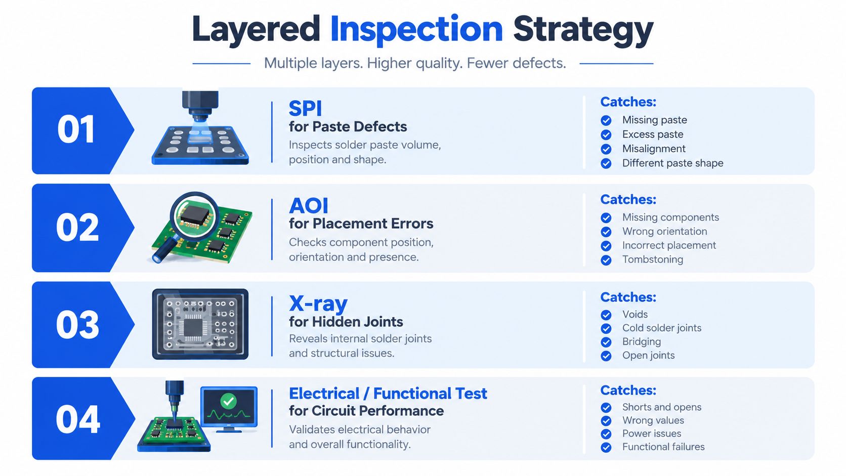
Use SPI measurements of volume, height, area, and positional offset before approving placement. Review distributions by package or pad family instead of accepting a board-level pass indicator that hides a marginal group of apertures.
- Insufficient deposition: Investigate aperture geometry, release, alignment, and printing setup before compensating elsewhere.
- Excess deposition: Review local aperture design and printing conditions rather than relying on post-reflow repair.
- Inconsistent deposition: Hold placement while the process engineer identifies the source of variation.
After placement, confirm polarity, reference designators, fiducial registration, and feeder setup before committing the board to reflow.
<a id="measure-the-boards-thermal-profile"></a>
Measure the board's thermal profile
Attach thermocouples at representative high- and low-thermal-mass locations. Validate the measured profile against the chosen alloy and component limits, not an oven recipe borrowed from an unrelated assembly.
Include the expected assembly sequence in that review. Require the process engineer to account for later heating operations and any components with restrictive handling or thermal requirements.
Process boundary: Oven settings describe the equipment. Thermocouple measurements describe what the assembly experienced.
Save the measured profile, thermocouple locations, and approved recipe with the build records. If the supplier changes the panel, paste, or thermal setup, require an assessment of whether profiling must be repeated.
<a id="buy-a-schedule-with-defined-prerequisites"></a>
Buy a schedule with defined prerequisites
Compare schedule options only after the supplier identifies what must be ready.
| Build Route | Use It When | Engineering Burden to Retain | |---|---|---| | Quick-turn | Files, materials and approvals are ready | Confirm inspection and profiling aren't omitted | | Standard scheduled build | You can accommodate normal engineering coordination | Close findings before the line slot | | Economy route | Delivery flexibility matters more than urgency | Obtain clear milestones and release conditions | | Consigned or kitted | Your team controls the supplied materials | Verify completeness, labeling and traceability | | Turnkey or partial turnkey | You want the supplier to source all or selected parts | Retain alternate approval and configuration control |
Ask for separate milestones for material readiness, fabrication, assembly, test, and dispatch. Board construction, finish, component availability, stencil decisions, test preparation, and shipping must all be accounted for in the quotation.
Don't purchase a short assembly promise and mistake it for a complete delivery commitment.
<a id="inspection-and-test-layers-that-catch-what-visual-checks-miss"></a>
Inspection and Test Layers That Catch What Visual Checks Miss
Inspection methods answer different questions. Require the supplier to define coverage by package and circuit risk rather than offer an unspecified inspection package.
Paste inspection provides upstream process evidence. Post-reflow inspection and electrical testing must establish what happened after placement and soldering, including defects that aren't visible from above.
Use a layered strategy to assign the right question to each method.
<a id="match-the-method-to-the-defect"></a>
Match the method to the defect
Specify AOI for visible placement and soldering defects. Require review of flagged conditions and disposition records, particularly when the inspection program is being established for a new revision.
For BGAs and bottom-terminated components, require X-ray inspection of hidden joints. An AOI pass isn't evidence that concealed connections meet the agreed acceptance criteria.
- Flying-probe testing: Ask the test engineer to define accessible nodes and the electrical checks the system can perform.
- ICT: Consider it where the design's access and fixture strategy support the intended checks.
- Boundary scan: Evaluate it for suitable devices and interconnections, with coverage stated explicitly.
- Functional testing: Supply operating conditions, stimulus, expected responses, firmware, and pass/fail limits.
Don't let a power-on check stand in for an application-specific test. A power board needs defined operating conditions; an RF assembly needs measurements suited to its intended behavior.
<a id="request-findings-not-just-stamps"></a>
Request findings, not just stamps
Ask for defect records organized by reference designator, package, operation, and revision. Separate defects caught before reflow from those found afterward, and distinguish inspection false calls from confirmed defects.
Use the resulting defect Pareto to assign corrective actions. A repeated placement escape requires a different response from a paste-transfer problem or a thermal excursion.
Require repaired boards to retain their rework history and retest status. Keep their measurements identifiable so engineering can decide whether they're suitable for debugging, validation, or neither.
The deliverable is a traceable explanation of build quality, not a certificate that conceals how much intervention was needed.
<a id="packaging-shipping-and-reading-the-prototype-result"></a>
Packaging, Shipping, and Reading the Prototype Result
The build isn't complete when the last board leaves test. Specify delivery condition before quoting: panelized or singulated, protected connectors, board identification, and whether engineering needs access to panel coupons or retained samples.
Require ESD-protective packaging and physical separation that prevents assemblies from contacting each other. Where moisture control is necessary, agree on moisture-barrier or vacuum-sealed packaging according to the applicable handling requirements, rather than requesting vacuum sealing indiscriminately.
<a id="ship-the-records-with-the-hardware"></a>
Ship the records with the hardware
Include first-article findings, inspection dispositions, test results, and approved deviations in the delivery package. Ensure each board's identifier maps to its configuration and repair history.
For urgent shipments, compare available express services by actual pickup arrangements, destination service, and customs handling. On cross-border orders, agree on the commercial description, declared value, origin information, consignee details, and responsibility for clearance before dispatch.
Don't promote a working board into a production baseline until you've reviewed how it was built.
<a id="apply-a-production-readiness-scorecard"></a>
Apply a production-readiness scorecard
Use status categories such as ready, conditional, and blocked. Don't average unresolved engineering risks into a reassuring overall score.
| Readiness Area | Evidence to Review | Corrective Action When Conditional or Blocked | |---|---|---| | Process capability | Stable printing, placement and thermal-process records | Resolve variation and confirm the revised setup | | Test coverage | Documented checks and explicit untested requirements | Add access, procedures or appropriate testing | | Traceability | Files, installed parts, firmware and deviations linked to boards | Reconstruct records or repeat the affected validation | | Repeatability | Consistent results without unexplained intervention | Investigate differences before production approval | | Production relevance | Compatible panel, assembly sequence and handling | Validate the intended production configuration |
A functional prototype can still give misleading validation data if technicians rely on hand rework, atypical parts, or a nonrepresentative thermal process. The prototype-assembly readiness discussion from Leadsintec identifies reflow survivability, BGA consistency, thermal performance, substitution effects, and production-tolerance reliability as issues that deserve explicit review.
Close each conditional item with an owner and required evidence. Release to production when your team can defend the manufacturing configuration and the conclusions drawn from it, not because the demonstration succeeded.
Lianyuhong Technology Co.,Ltd offers PCB fabrication, design and layout, SMT stencils, and turnkey SMT and THT assembly for prototype and production builds. Visit Lianyuhong Technology Co.,Ltd with your controlled file package, critical-component restrictions, and test requirements, and request an engineering review that defines the build process, inspection scope, and delivery records before you place the order.