
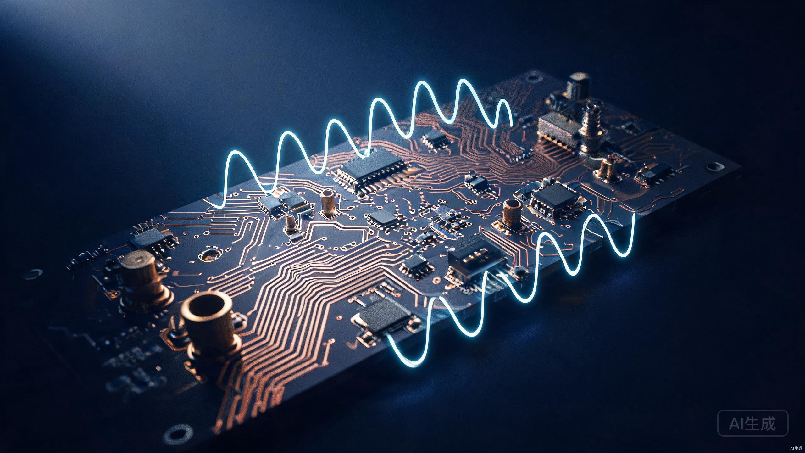
Ceramic PCB Manufacturing
Ceramic PCB manufacturer offering ceramic PCB board and ceramic PCB material (Al2O3, AlN, BeO) with Direct Bond Copper (DBC) and thick film technology for high-power, high-temperature and thermal management applications.
What Is a Ceramic PCB?
A ceramic PCB replaces the organic FR-4 substrate with a ceramic substrate — most commonly alumina (Al2O3), aluminium nitride (AlN) or beryllium oxide (BeO). The ceramic is not just a carrier; it is the thermally conductive, electrically isolating foundation of the circuit. Copper is applied by Direct Bond Copper (DBC), thick-film printing or thin-film deposition, producing a ceramic circuit board that handles heat, voltage and temperature that organic laminates cannot.
Ceramic substrate matters for three engineering reasons: thermal conductivity that is tens to hundreds of times higher than FR-4, a coefficient of thermal expansion (CTE) that matches silicon and copper to protect solder joints, and the ability to operate continuously above 300°C. That combination makes ceramic PCB boards the substrate of choice for high-power LED, power electronics, RF, medical and high-temperature applications.
Why Ceramic Substrate Matters
Three reasons ceramic is chosen over FR-4 and metal-core boards for demanding thermal and high-temperature designs.
Exceptional Thermal Conductivity
Ceramic PCB material dissipates heat far better than FR-4 or metal-core boards. Alumina (Al2O3) reaches ~24 W/mK and aluminium nitride (AlN) up to 280 W/mK, keeping high-power junctions cool without forced airflow or bulky heatsinks.
CTE Matching to Silicon
The coefficient of thermal expansion of ceramic substrate closely matches silicon die and copper, reducing mechanical stress at solder joints during thermal cycling — critical for power devices and LED chips mounted directly on the board.
High-Temperature Operation
Ceramic PCB boards operate continuously above 300°C where organic substrates delaminate or char. This makes ceramic the substrate of choice for high-temperature automotive, downhole and aerospace electronics.
Ceramic PCB Applications
Device categories where ceramic substrate is typically not optional.
High-Power LED
High-luminance LEDs mount directly on ceramic substrate for efficient heat spreading. DBC ceramic PCBs handle multi-chip LED arrays with minimal thermal resistance and long lumen-maintenance life.
Power Electronics
Power modules, MOSFET and IGBT packages use DBC ceramic boards to combine thick copper traces with high dielectric strength and thermal conductivity for high-current switching stages.
Automotive
Engine-bay and powertrain modules exposed to high ambient temperatures and thermal cycling rely on ceramic PCB boards for reliability. See our automotive PCB solutions for more.
Automotive PCB solutionsRF & Microwave
Low dielectric loss and stable permittivity make thin-film ceramic substrate ideal for RF, microwave and mmWave circuits where substrate consistency directly affects impedance.
Medical Sensors
Implantable and diagnostic sensors benefit from ceramic's biocompatibility, thermal stability and electrical isolation for compact, reliable sensing modules.
Aerospace & Military
Rugged high-temperature and high-reliability applications — radar, avionics and downhole instrumentation — use ceramic circuit boards where organic laminates cannot survive the environment.
Ceramic PCB Manufacturing Capabilities
The full technical envelope for ceramic circuit boards — from substrate material and construction type to copper weight and surface finish.
| Parameter | Capability |
|---|---|
| Substrate Materials | Al2O3 96%, Al2O3 99.5%, AlN, BeO |
| Construction Types | Direct Bond Copper (DBC), Thick Film, Thin Film |
| Copper Weight | up to 12 oz (420 μm) for DBC |
| Thermal Conductivity | 24 – 280 W/mK (material dependent) |
| Operating Temperature | up to 300°C (continuous) |
| Board Thickness | 0.25 – 3.0 mm |
| Min Line / Space | 0.1 / 0.1 mm (thick film); finer for thin film |
| Max Panel Size | 139 × 190 mm (DBC standard) |
| Surface Finish | ENIG, Immersion Silver, Gold, OSP |
| Electrical Test | 100% flying-probe / fixture-based test |
| Dielectric Strength | ≥ 10 kV/mm (Al2O3) |
| Thermal Cycling | rated for -55°C to +300°C cycles |
- Al2O3 96% / 99.5%, AlN and BeO substrate options
- DBC, thick-film and thin-film construction
- Heavy copper up to 12 oz for high-current power stages
- 100% electrical test on every ceramic PCB board
Ceramic PCB Types We Build
Three construction methods covering the full range of current, density and frequency requirements.
Direct Bond Copper (DBC)
Thick copper foil is bonded directly to the ceramic substrate at high temperature through an eutectic process. DBC delivers heavy copper (up to 12 oz) for high-current power modules and excellent thermal performance for LED arrays and IGBT power stages.
Thick Film Ceramic
Conductive and resistive pastes are screen-printed onto the ceramic substrate and fired, forming traces and resistors in one process. Thick film is suited to hybrid circuits, sensors and LED boards where moderate current density and integrated resistors are needed.
Thin Film Ceramic
Sputtered or evaporated metal layers are deposited and etched on the ceramic substrate, achieving very fine line/space and tight impedance control for RF, microwave and high-frequency precision circuits.
Why Choose a Ceramic Circuit Board
The engineering advantages that justify ceramic substrate over organic alternatives.
Thermal Management
Ceramic PCB material conducts heat 20-200× better than FR-4, letting high-power devices run cooler on a smaller footprint without additional heat-spreading layers.
CTE Matching
Ceramic substrate expands and contracts at a rate close to silicon and copper, protecting solder joints from fatigue during repeated thermal cycling.
High Temperature
With continuous operating capability above 300°C, ceramic PCB boards survive environments that would delaminate or degrade organic laminates.
Electrical Isolation
High dielectric strength (≥10 kV/mm for alumina) provides reliable electrical isolation between high-voltage circuit blocks on a single ceramic circuit board.
Related Solutions
Complementary capabilities and services for ceramic PCB projects.
Metal-Core PCB (MCPCB)
An alternative thermal-management solution — aluminium or copper base boards for mid-power LED and power applications where cost matters.
Learn moreLow-Volume PCB Assembly
Once your ceramic PCB design is validated, scale up with low-volume assembly for pilot runs and engineering builds.
Learn moreMedical PCB Assembly
Ceramic substrate is widely used in medical sensors — explore our medical-grade PCB assembly capabilities.
Learn moreCeramic PCB FAQ
Common questions about ceramic substrate, construction types and applications.
A ceramic PCB (ceramic circuit board) replaces the organic FR-4 or metal-core substrate with a ceramic substrate such as alumina (Al2O3), aluminium nitride (AlN) or beryllium oxide (BeO). Ceramic PCB material offers far higher thermal conductivity, a coefficient of thermal expansion that matches silicon, and the ability to operate above 300°C, making it the substrate of choice for high-power, high-temperature and LED applications. Construction types include Direct Bond Copper (DBC), thick film and thin film.
Direct Bond Copper (DBC) bonds thick copper foil (up to 12 oz / 420 μm) to the ceramic substrate through a eutectic process, giving high current capacity and excellent thermal performance for power modules and multi-chip LED arrays. Thick film ceramic screen-prints conductive and resistive pastes onto the substrate and fires them, producing traces plus integrated resistors in one process — suited to hybrid circuits and sensors with moderate current. DBC carries more current; thick film enables integrated passives.
FR-4 typically manages 0.3-0.4 W/mK and metal-core PCBs (MCPCB) around 1-4 W/mK (limited by the dielectric layer). Ceramic PCB material is far higher: alumina (Al2O3) reaches roughly 24 W/mK, aluminium nitride (AlN) up to 280 W/mK, and beryllium oxide (BeO) higher still. Because the ceramic is the substrate itself, there is no low-conductivity dielectric interface between copper and the heat-spreading layer.
Ceramic PCB cost depends on substrate material (Al2O3 is most economical; AlN and BeO command a premium), construction type (DBC, thick film or thin film), copper weight, panel size and order volume. Because ceramic substrates are harder to process than FR-4, ceramic PCB boards are generally a higher-cost option selected for applications where thermal or high-temperature performance is essential. Request a ceramic PCB RFQ with your stack-up and quantity for a detailed quote.
High-luminance LEDs generate significant heat at the junction, and even small thermal resistance reduces lumen output and lifetime. Ceramic PCB material — especially DBC alumina or AlN — spreads heat directly under the LED chip with minimal interface resistance, supports direct chip-on-board mounting, and matches the LED's CTE to protect solder joints. This keeps junction temperature low and maintains lumen maintenance over a long operating life.
Yes. DBC ceramic PCB boards are the standard substrate for power modules — MOSFET, IGBT and diode packs — because thick bonded copper (up to 12 oz) handles high current while the ceramic provides high dielectric strength and thermal conductivity. The CTE match to silicon die reduces stress at the die-attach interface during power cycling, improving module reliability.
There is no fixed minimum — prototype and small-batch ceramic PCB orders are welcome. Whether you need a few DBC prototypes for LED evaluation or a pilot batch of thick-film sensors, submit your Gerber/stack-up and quantity through a ceramic PCB RFQ and our team will confirm lead time and feasibility.
Start Your Ceramic PCB Project
Send your ceramic substrate, construction type (DBC / thick film / thin film) and stack-up — get a ceramic PCB quote within 24 hours.