
An RF board can look clean in simulation, pass a schematic review, and still behave differently on the bench. The first suspicion is often the layout, but the material and the fabrication process can shift impedance and loss too. Before changing traces, it helps to ask a more basic question: what does “Rogers PCB” mean?
A Rogers PCB isn't necessarily made by Rogers. The term usually describes a finished board fabricated by a PCB manufacturer using Rogers high-frequency laminate. That distinction matters when you're choosing a supplier: the laminate maker and the fabricator do different jobs, and both affect the finished result.
Table of Contents
- What Rogers PCBs Are and Where the Materials Come From
- When Rogers Materials Earn Their Place in a Design
- Manufacturing Steps Rogers Boards Demand
- How to Qualify a Rogers PCB Manufacturer
- Proving RF Performance Before Production Release
- Managing Lead Times and Material Substitutions
- Design and DFM Tips That Prevent Costly Respins
- Procurement Checklist and Next Steps for Your Rogers Build
<a id="what-rogers-pcbs-are-and-where-the-materials-come-from"></a>
What Rogers PCBs Are and Where the Materials Come From
Think of the laminate as a specialized ingredient and the fabricator as the maker who turns it into a finished product. Rogers supplies engineered materials; a PCB manufacturer converts those materials into a board through processes such as lamination, drilling, plating, imaging, and testing. If the board's electrical behavior doesn't match the design, the cause might lie in material properties, fabrication choices, or the way the two interact.
That's why a Rogers PCB isn't just a board carrying a brand name. It's a PCB built with a particular laminate system chosen for the electrical and mechanical demands of its application. Manufacturers use these materials for specialized circuits such as RF, microwave, antenna, radar, telecommunications, and other high-speed designs. Rogers is primarily a materials and components supplier, not a conventional bare-board fabrication house.
<a id="a-long-industrial-history-behind-modern-rf-boards"></a>
A long industrial history behind modern RF boards
Rogers traces its origins to 1832, when Peter Rogers founded the Rogers Paper Manufacturing Company. The business began with paperboard activities and later evolved into a manufacturer of engineered materials for electronics, mobility, and power applications. Its history shows how a company rooted in an earlier industrial era became part of the supply chain for modern electronics. Rogers' company history documents that development.
A milestone came in 1967, when Rogers expanded its Advanced Connectivity Solutions facilities to Arizona. That expansion indicates that electronics materials had become an established strategic activity by the late 1960s. Today, advanced engineered laminates are a major part of the company's portfolio, including materials used in high-frequency circuit boards.
For a product team, the important distinction is practical. Rogers provides a material platform. The PCB fabricator has to build the board to the design's layer structure, trace geometry, and performance requirements. A strong material specification doesn't, by itself, demonstrate that a particular factory can repeatedly manufacture your stack-up.
The path to a sound supplier decision starts with choosing the material for the job, then understanding how the board is built. From there, qualify the fabricator with evidence, verify the first article, and agree on how any proposed material substitution will be reviewed before procurement commits.
<a id="when-rogers-materials-earn-their-place-in-a-design"></a>
When Rogers Materials Earn Their Place in a Design
A high-frequency laminate earns its place when the electrical behavior of the material matters enough that a standard FR-4 stack-up no longer gives the design the margin it needs. There isn't one universal frequency at which every FR-4 design becomes unsuitable. The decision depends on the design's loss budget, geometry, operating frequency, and how tightly the team must control impedance.
The analogy is a road with changing surface conditions. A small variation might not matter at low speed, but at higher speed the same variation has a larger effect on the journey. In a circuit, dielectric constant affects how a signal travels and how a trace's geometry relates to its impedance. Dielectric loss reduces signal amplitude, and that loss becomes more consequential at microwave frequencies.
For example, the RO4000 family includes RO4003C and RO4350B. Their published electrical values show that both are designed for controlled high-frequency use, but they aren't identical. Rogers' RO4003C laminate information gives the RO4003C figures below, while the verified RO4350B figures provide a useful comparison.
| Attribute | RO4003C | RO4350B | |---|---:|---:| | Process dielectric constant at 10 GHz | 3.38 ± 0.05 | 3.48 ± 0.05 | | Typical dissipation factor at 10 GHz | 0.0027 | 0.0037 |
<a id="how-to-read-the-comparison"></a>
How to read the comparison
The process dielectric constant, often shortened to Dk, describes a material property used in designing the board. The stated tolerance matters because impedance depends on the relationship among dielectric constant, trace geometry, and dielectric thickness. A tighter, well-understood material value helps the design team and fabricator work from a more predictable electrical basis. The data also distinguishes process Dk from design Dk, so use the value appropriate to the manufacturer's design guidance rather than assuming that one figure serves every calculation.
The dissipation factor, or Df, indicates dielectric loss. At microwave frequencies, loss in the dielectric can reduce signal amplitude and efficiency. RO4003C has a lower stated typical Df than RO4350B under the same frequency condition, but the right choice still depends on the circuit's requirements and the full stack-up, not on one table entry alone.
RO4350B can be processed using methods similar to standard epoxy/glass PCB materials, according to Rogers. That may help a manufacturer work with familiar fabrication workflows while using a laminate selected for high-frequency performance. For designs that need a supplier with dedicated high-frequency capabilities, a high-frequency PCB fabrication service is a sensible place to begin a stack-up discussion.
Don't make the decision on electrical values alone. Material availability, fabrication familiarity, cost, and the consequences of a hybrid stack-up all matter. Choose the laminate because it supports the design's measured requirements, not because its name sounds like a safer option.
<a id="manufacturing-steps-rogers-boards-demand"></a>
Manufacturing Steps Rogers Boards Demand
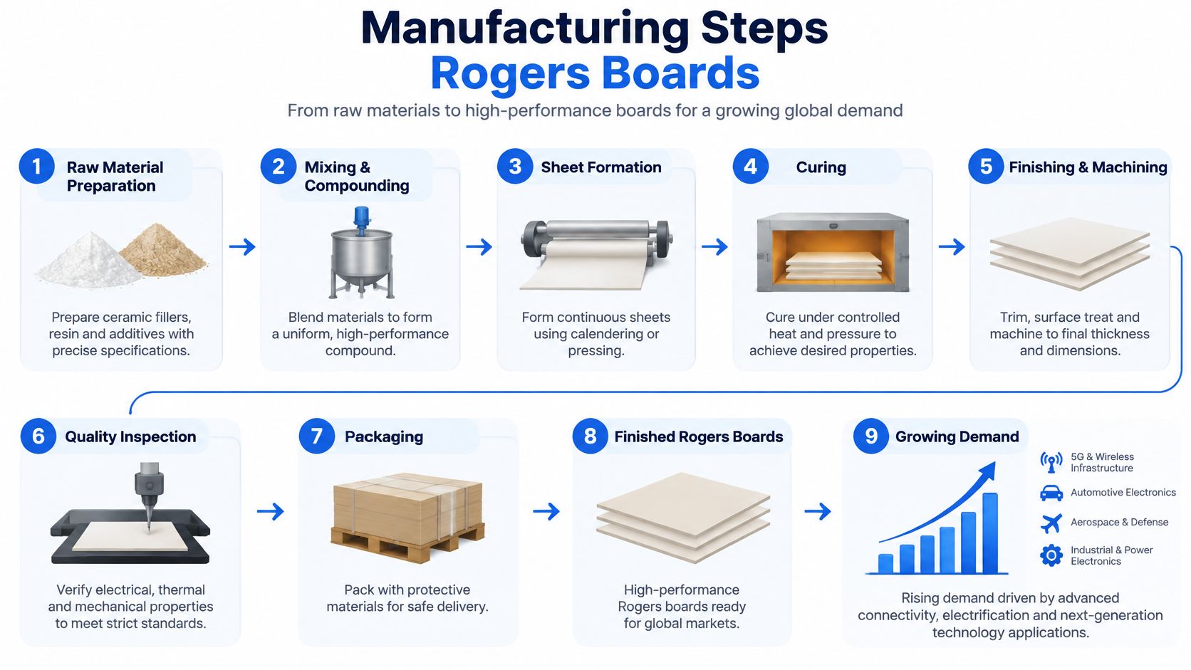
Building a high-frequency board is a bit like assembling a precision instrument from pre-measured parts. Each dimension needs to stay close to the design intent, because a change in dielectric thickness, copper geometry, or layer registration can change the electrical result. The process begins before the fabricator images a circuit pattern.
<a id="from-incoming-material-to-a-bonded-stack-up"></a>
From incoming material to a bonded stack-up
First, the factory receives and identifies the laminate. The team needs to know which grade and thickness it has received, and it must handle and store the material according to its requirements. If the wrong material or construction enters production, downstream process control can't restore the intended electrical properties.
Next comes the stack-up, the planned arrangement of copper and dielectric layers. The design team and fabricator need to agree on the actual material, copper, finished dielectric thickness, and bonding approach. This is especially important for hybrid boards that combine Rogers and FR-4. Different materials can behave differently during lamination; resin flow, pressure, and layer registration affect the finished structure.
Lamination bonds the layers into a solid panel. The fabricator's process must preserve the layer spacing and alignment the design depends on. Small changes can affect impedance, so a supplier's ability to build a particular hybrid stack-up is more meaningful than a general statement that it can process Rogers.
<a id="patterning-drilling-and-inspection"></a>
Patterning, drilling, and inspection
After lamination, imaging and etching create the conductive traces. The fabricator controls the trace geometry that, together with the material and dielectric thickness, helps establish impedance. Drilling then creates openings for plated connections between layers. Boards with HDI features, microvias, or fine lines add further demands: the factory must manage those structures while preserving the RF design's electrical requirements.
Plating adds conductive copper inside drilled holes and across selected surfaces. Optical inspection can catch visible pattern or registration defects, while electrical testing checks for continuity and shorts. Those checks are necessary, but they don't replace evidence that the finished board meets its intended RF behavior. A capable manufacturer should be able to explain which checks apply to the specific board, not just point to a general process diagram.
When you review a supplier's process, ask how it controls the points where the electrical design can drift: material identity, final dielectric thickness, registration, trace formation, and the finished plated structure. The answer should connect the steps to your actual stack-up, not only describe the factory's standard workflow.
The video below offers a visual overview of a Rogers PCB manufacturing process.
<iframe width="100%" style="aspect-ratio: 16 / 9;" src="https://www.youtube.com/embed/Ykr6UYe-3H0" frameborder="0" allow="autoplay; encrypted-media" allowfullscreen></iframe><a id="how-to-qualify-a-rogers-pcb-manufacturer"></a>
How to Qualify a Rogers PCB Manufacturer
A purchasing team sends the same Gerber package to three fabricators. Two reply "Rogers-capable" within a day. The third replies with questions about dielectric thickness tolerance, copper foil type, and whether the design mixes FR-4 with the RF laminate in one stack-up. That third response deserves attention, because qualifying a Rogers manufacturer works like an engineering interview: the quality of the questions tells you more than the polish of the answers.
Use a consistent set of criteria so each supplier is judged on the same ground.
| Criterion | What to ask | Useful evidence | |---|---|---| | Capabilities | Has the factory built this exact Rogers grade, thickness, copper foil, via structure, and hybrid stack-up? | Examples of comparable constructions, documented stack-ups, and engineering feedback on your design | | Certifications | Which processes and management systems do the certificates actually cover? | Current certification scope matched against your board's requirements | | Verification | What does the factory measure on a first article before releasing production? | A written test plan tied to your stack-up and impedance targets | | Lead times | How does material availability shape the schedule? | A quotation that names lead-time options and material assumptions | | Supply chain | How is the material lot identified and traced? | Traceable lot records and a written substitution policy |
<a id="separate-capability-from-credentials"></a>
Separate capability from credentials
Capabilities need specifics. "We can process Rogers" says nothing about whether the factory has run your laminate grade, dielectric thickness, copper weight, via arrangement, or operating frequency. Ask the supplier to review the actual stack-up and name the process risks before production files go out. A fabricator that only quotes fast is guessing.
Certifications work like a driver's license. Passing the exam proves the driver met a standard on test day; it says little about whether they have driven your specific route in bad weather. A certificate shows a management system was assessed. The open question is whether the factory can hold the dimensions and deliver the verification your board requires.
Lianyuhong Technology Co.,Ltd is a UL recognized PCB manufacturer and uses RoHS- and REACH-compliant materials. Those credentials address supplier qualification and material compliance at the management-system level, leaving the RF-performance question to board-level evidence. Buyers can review the company's published certification information, then request the measurements their own design calls for.
<a id="set-the-substitution-rules-before-you-need-them"></a>
Set the substitution rules before you need them
Lead time and supply chain deserve the same scrutiny as process capability. High-frequency laminates can carry longer procurement cycles, minimum-order constraints, and storage requirements, so ask what material assumptions a quotation makes and how each lot will be identified. A prepared supplier will define a substitution path in advance: which alternative grades are acceptable, who approves the change, and what re-verification the swap triggers. An undocumented substitution is how a board passes continuity testing and still misses its impedance budget.
Practical rule: A certification helps you assess the supplier's systems. A first-article test plan helps you assess the board you're buying.
<a id="proving-rf-performance-before-production-release"></a>
Proving RF Performance Before Production Release
Qualifying a supplier and qualifying a specific PCB are related, but they're not the same exercise. One asks whether a factory has appropriate capabilities. The other asks whether the completed board, built with a traceable material lot and a defined process, meets the design's requirements.
Think of a laminate specification as a description of the ingredient and a board specification as an assessment of the finished dish. The base-material standard IPC-4103 addresses high-frequency laminate requirements. The completed-board standard IPC-6018D addresses RF and microwave boards, including electrical and mechanical performance, thermal stress, and test coupons. A material datasheet can't substitute for evidence about your finished construction.
<a id="build-an-evidence-matrix-not-a-paper-file"></a>
Build an evidence matrix, not a paper file
Ask for evidence tied to the question it answers. A lot-specific certificate of conformity and material traceability connect the build to the intended laminate and reduce the risk of an unapproved material entering production. Controlled-impedance coupons provide a structure for checking whether the board's transmission-line behavior aligns with the specified impedance.
A cross-section reveals physical details such as dielectric thickness, layer arrangement, plating, and registration. That evidence can expose construction differences that a datasheet won't show. Plating evidence helps confirm that the plated features were produced and evaluated against the board's requirements.
For impedance verification, time-domain reflectometry, or TDR, is a non-destructive method. It helps the buyer assess impedance behavior without cutting the board apart. Where the operating frequency is above 10 GHz, request measured S-parameters as part of the evidence rather than relying only on a datasheet Dk or Df value. The data should be associated with the relevant board, coupon, and build conditions so the team can interpret it correctly.
<a id="release-the-first-article-against-the-real-stack-up"></a>
Release the first article against the real stack-up
First-article validation should happen before production release. Review the cross-section and electrical results together: the cross-section helps show what the factory built, while electrical measurements show how that construction behaves. For mixed FR-4 and Rogers stack-ups, this matters even more because resin flow, layer registration, and copper roughness can affect insertion loss and impedance.
Lianyuhong states that every board is manufactured to IPC-2 or IPC-3 standards with 100% AOI, flying-probe, and electrical testing. Those checks support board inspection and electrical verification, but the project should still define any RF-specific coupons or measurements required for release. For background on how impedance requirements fit into PCB design and verification, see this guide to impedance control in PCB manufacturing.
Put the evidence requirements in the purchase documentation. If you leave them as an informal expectation, the supplier may complete its standard checks without producing the measurements your RF team needs to approve the build.
<a id="managing-lead-times-and-material-substitutions"></a>
Managing Lead Times and Material Substitutions
Rogers isn't automatically the lowest-risk choice. A specified material can be the right electrical fit and still create a procurement problem if it isn't available when the design is frozen. Lead times, minimum-order constraints, storage conditions, and lot traceability can affect the schedule, so a sourcing plan should be part of the engineering decision rather than an afterthought.
The question isn't “Rogers or FR-4?” It's whether a proposed alternate can be used without invalidating RF performance, compliance, or existing qualification evidence. A drop-in substitution is one the design team has already assessed and approved for the relevant construction. A non-drop-in change alters a design assumption and requires engineering review before release.
<a id="compare-the-whole-construction"></a>
Compare the whole construction
Don't judge an alternate by its material-family name or headline Dk alone. Compare its dielectric constant and dissipation factor, thickness tolerance, copper roughness, thermal expansion, moisture behavior, peel strength, and availability at the operating frequency. The board's electrical behavior depends on the relationship among material, geometry, copper, and stack-up.
Hybrid constructions carry particular risk. Changing a bonding material or prepreg can alter resin content, final dielectric thickness, impedance, and lamination pressure. A substitute that appears similar on a purchasing description may still change the manufactured stack-up.
Use a clear decision path:
- If the exact grade and construction remain available, retain the approved material and document the lot and schedule assumptions.
- If a proposed alternate has already been characterized for the same construction, compare its properties and confirm that the existing qualification evidence still applies.
- If the alternate changes dielectric properties, thickness, copper, or bonding materials, pause procurement approval and send the change for engineering review.
- If the design is hybrid or operates at a demanding frequency, treat substitution as a design change unless the team has evidence that the alternate preserves performance.
A technically validated alternative can reduce continuity or schedule risk. An unvalidated substitute can create RF requalification work and delay the build. Before approving a change, agree on the minimum re-test plan: review the revised stack-up and material records, inspect the first article, and repeat the electrical measurements needed to establish that the board still meets its requirements.
Don't let a purchase-order description become an engineering approval. Record who can authorize a substitution and what evidence that decision requires.
<a id="design-and-dfm-tips-that-prevent-costly-respins"></a>
Design and DFM Tips That Prevent Costly Respins
A design-for-manufacturing review works best before the layout is frozen. The goal isn't just to find violations; it's to expose decisions that may become expensive once the design reaches the fabricator. In high-frequency work, a schematic review can confirm connectivity while missing the stack-up and geometry details that determine whether the board can meet its electrical intent.
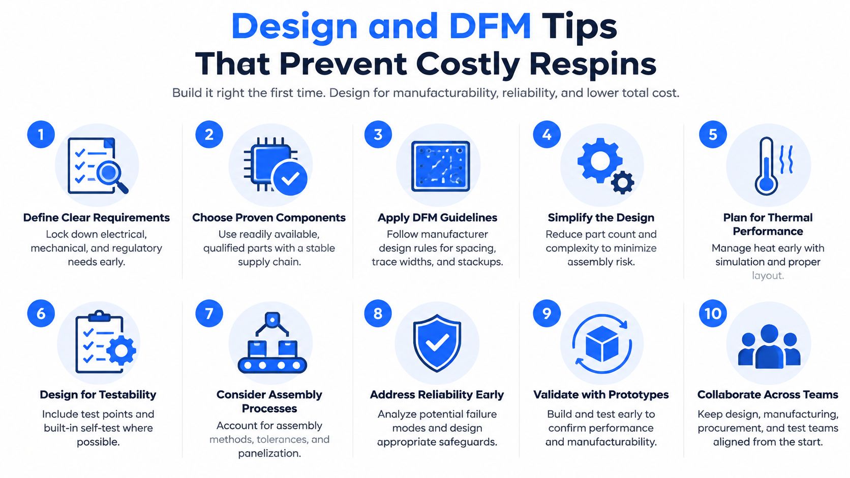
Start by selecting the stack-up with the fabricator in mind. Share the intended laminate grade, copper, layer sequence, and finished dielectric thickness early enough for the manufacturer to identify any construction constraints. If the design mixes FR-4 and Rogers, ask the factory to review resin flow and layer registration as part of its stack-up feedback.
<a id="decide-electrical-targets-using-real-construction-inputs"></a>
Decide electrical targets using real construction inputs
Define impedance using the actual laminate and planned stack-up, not only a nominal dielectric constant. Trace geometry, copper characteristics, and dielectric thickness all contribute to the result. If the fabricator proposes a different thickness or construction to improve manufacturability, have the team reassess the impedance rather than assuming the change is electrically neutral.
Copper roughness also affects signal behavior, especially as frequency rises. Via transitions need attention because a signal moving between layers encounters a change in its path and surrounding structure. These effects don't mean that every transition is a problem. They mean the design should include the actual geometry and frequency requirements in its review.
Send the factory the impedance targets and the expected test-coupon details at the start of the project. A coupon can only help verify the design if the manufacturer knows what to build and what result the engineering team needs to review. Identify the test method and the acceptance criteria in the project documentation rather than relying on a general request for “impedance control.”
A useful DFM review should return specific feedback: whether the requested construction is buildable, whether component availability affects the planned assembly, which layout or stack-up constraints need attention, and what changes could affect electrical performance. Ask the fabricator to distinguish manufacturing recommendations from changes that need design approval. That keeps a convenient process adjustment from becoming an undocumented change to the RF design.
The earlier those decisions are shared, the less likely the team is to discover a material or geometry conflict after ordering. A DFM review can't guarantee performance, but it can make the assumptions visible while the design is still easy to change.
<a id="procurement-checklist-and-next-steps-for-your-rogers-build"></a>
Procurement Checklist and Next Steps for Your Rogers Build
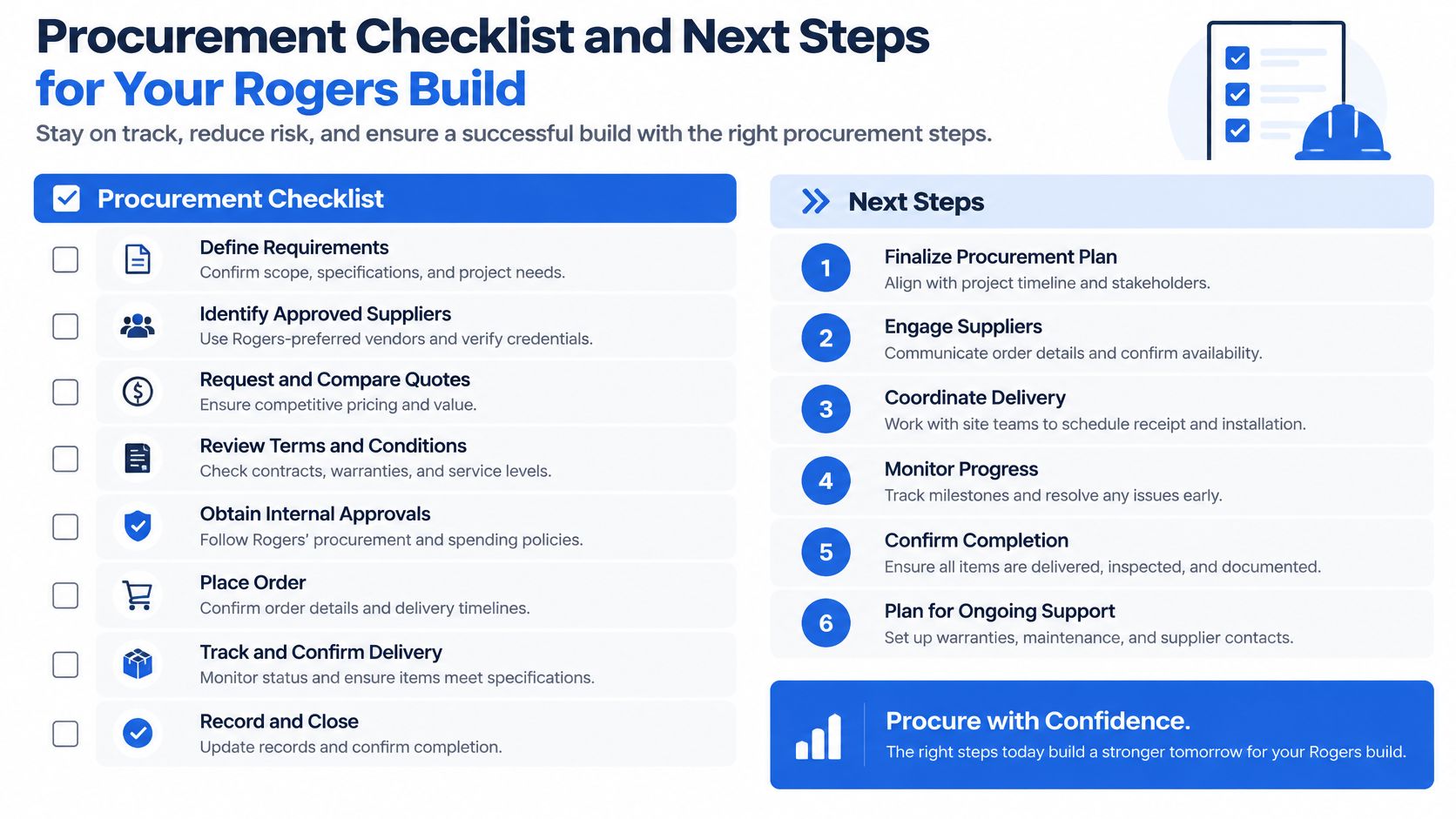
A sound purchase decision ties the material specification to the board's acceptance evidence. Before placing an order, make sure the engineering team and procurement team are working from the same approved stack-up, material grade, and test plan. That avoids a common mismatch: engineering approves one construction while purchasing receives a quotation based on another.
<a id="confirm-the-build-before-you-commit"></a>
Confirm the build before you commit
Use this checklist to make the purchase decision concrete:
- Stack-up and material: Name the Rogers grade, thickness, copper, layer arrangement, and any hybrid bonding materials.
- Impedance and coupons: Specify targets, tolerances, coupon construction, and the evidence required to review the result.
- First article: Agree on the cross-section, electrical tests, and any RF measurements needed before production release.
- Certificates and traceability: Request lot-specific certificates of conformity and records linking the material to the board build.
- Substitution policy: Define which alternates are approved and which changes require engineering review and re-testing.
- Lead-time commitment: Confirm the material assumptions behind the schedule and how the supplier will notify you if availability changes.
Ask direct questions: Which Rogers grades and thicknesses has the factory built in constructions comparable to yours? What evidence will it provide before production release? How does it review and document a material-substitution request? Those questions move the discussion beyond a generic claim of Rogers capability.
Lianyuhong Technology Co.,Ltd fabricates high-frequency PCBs in-house alongside HDI, flexible, and metal-core boards. Its turnkey assembly covers prototypes through production with no minimum order quantity, and fabrication and assembly operate under one quality system. The workflow has four steps: upload Gerber, BOM, and pick-and-place files through a secure portal; engineers review the design and component availability for DFM feedback; receive a detailed quotation with transparent pricing and lead-time options; then have the boards manufactured, assembled, tested, and shipped worldwide.
Use that workflow to resolve open questions before a design freeze. Your RF team should review the stack-up and acceptance evidence, while procurement confirms material availability and the substitution policy. The decision is ready when both groups can point to the same construction and know what results must be approved before production.
Upload your current Gerber, BOM, and pick-and-place files for a DFM review before committing to a Rogers stack-up. Lianyuhong Technology Co.,Ltd can review the design and component availability, then provide a quotation with lead-time options for your build.