
A black PCB board uses black solder mask over its copper and laminate. The color changes appearance and inspection contrast, not the board's electrical performance. Black mask reflects far less visible light than green mask, which makes inspection planning more important than claims about premium performance.
Choose the construction for performance and the finish for appearance. Then qualify the manufacturing process: designers and buyers should consider inspection coverage, manufacturable clearances, delivered cost, and environmental validation.
Table of Contents
- What Makes a Black PCB Board Black
- Where Black Boards Show Up in Real Products
- Black Versus Green Mask on Yield and Inspection
- What Black Mask Adds to Board Cost
- Heat and Reliability Myths Versus Evidence
- Inspecting, Assembling and Designing Black Boards
- Deciding Whether to Specify a Black Board
<a id="what-makes-a-black-pcb-board-black"></a>
What Makes a Black PCB Board Black
The black surface is normally solder mask, a permanent protective coating over the copper circuitry. It isn't evidence of a special black laminate, heavier copper, or a different electrical architecture.
Underneath, the board still has a base material such as FR-4 or high-Tg FR-4, patterned copper, and openings where components and test probes need electrical access. The mask protects covered circuitry against oxidation, moisture, dust, chemicals, and handling damage, as described in AdvancedPCB's solder-mask guide. It doesn't replace the laminate or the metallic surface finish applied to exposed pads.
What black solder mask changes and what it leaves alone
| Factor | Changed by black mask? | Why it matters | |---|---|---| | Solder mask color | Yes | Appearance, glare, and branding | | Base laminate (FR-4 or high-Tg FR-4) | No | Sets the dielectric and thermal base | | Copper weight and trace geometry | No | Sets current capacity and impedance | | Electrical performance | No, in general | Driven by construction, not mask color | | Optical inspection contrast | Yes | Lower contrast makes defects harder to see | | Protection against oxidation and moisture | No, if the mask is qualified | Controlled by mask material and process quality |
<a id="specify-the-finish-separately-from-the-construction"></a>
Specify the finish separately from the construction
A drawing that says only “black PCB” leaves important decisions unresolved. Specify the laminate, stack-up, copper requirements, impedance requirements, exposed-pad finish, and acceptance criteria independently. Then identify the solder-mask color and whether the required appearance is glossy or matte.
Green remains the manufacturing default because fabricators have a long process history with it, broad material availability, and useful inspection contrast. Black is an established alternative, not a different grade of circuit board.
Specification rule: Treat black as a cosmetic and process requirement, not as shorthand for electrical quality.
That distinction also prevents purchasing substitutions. A visually similar black board isn't equivalent if its dielectric material, copper construction, or surface finish changes. Conversely, a green board built to the same electrical requirements doesn't become electrically inferior because its color is less aligned with the product design.
<a id="where-black-boards-show-up-in-real-products"></a>
Where Black Boards Show Up in Real Products
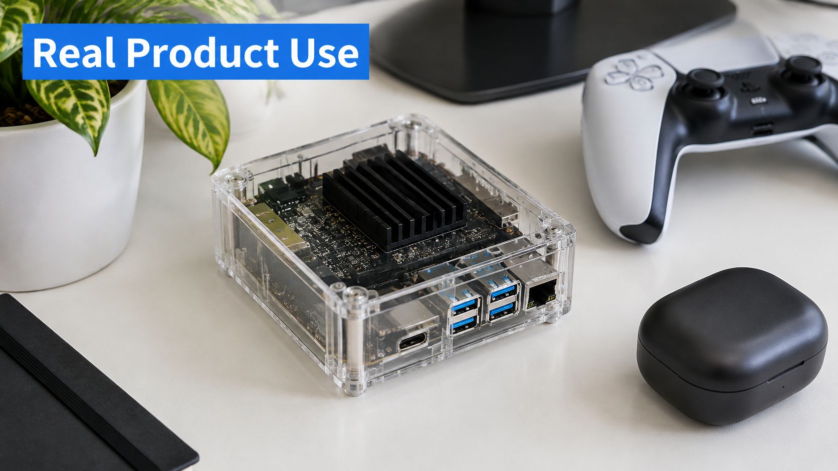
Consider a handheld controller with a translucent housing and an exposed board edge beside its display. The industrial designer wants the internal electronics to disappear into the enclosure rather than create a bright green border. Black mask serves a clear purpose because the customer sees the board during normal use.
A transparent computer enclosure makes the same choice more prominent. The PCB, heatsink, connectors, and mounting hardware form part of the product's visible composition.
<a id="visible-hardware-versus-enclosed-electronics"></a>
Visible hardware versus enclosed electronics
For premium audio equipment or gaming hardware, a dark board can support a coordinated appearance. In a control panel or display module, reducing visible reflections around an aperture can also justify the finish. Branded industrial equipment may use black to keep exposed electronics visually consistent with the enclosure.
Now consider a sealed industrial sensor. The user never sees its PCB, and service technicians access it only during troubleshooting. Unless the product has another optical requirement, green is the sensible starting point because there's no customer-facing benefit to offset the inspection work.
LED and power assemblies need a separate judgment. A metal-core or thick-copper board may use black to match the housing, but the designer still has to engineer the heat path through the substrate, interfaces, and enclosure.
Before assigning a color, answer these questions:
- Visibility: Will users see the board face or its routed edges?
- Branding: Does the appearance contribute to the product customers buy?
- Optical function: Is reflected light near a display or opening a genuine concern?
- Inspection access: Are dense components already making defect detection difficult?
Black works best when it solves an identifiable presentation problem. It isn't a performance upgrade merely because it looks deliberate.
<a id="black-versus-green-mask-on-yield-and-inspection"></a>
Black Versus Green Mask on Yield and Inspection
Black mask changes the inspection and process margin, not the board's electrical function. The practical difference depends on copper weight, artwork geometry, mask formulation, and the fabricator's qualified process.
| Metric | Green mask | Black mask | Condition or note | |---|---|---|---| | Reflectance | Higher | About 5–10% | Dark pigment absorbs visible light | | Contrast against exposed copper | Higher | About 1.5:1 | Can approach conventional AOI detection limits | | First-pass yield | 95–98% | About 2–3 percentage points lower | Four-layer board, 6/6 mil traces, 0.5 mm BGA | | Solder bridge spacing | 0.19 mm | About 0.22 mm | 1 oz outer copper | | Solder bridge spacing for matte black | About 0.30 mm | About 0.35 mm | 3 oz outer copper | | Solder mask dam | About 100–125 µm preferred | About 100–125 µm preferred | Registration around ±38 µm for demanding designs |
The reflectance, contrast, yield, spacing, dam, and registration figures are reported in LTP's solder-mask color comparison. The cited yield comparison uses a four-layer board with 6/6 mil traces and a 0.5 mm BGA; the spacing figures depend on outer copper weight. Treat these as process-dependent planning values, not universal acceptance limits.
<a id="why-the-process-window-gets-tighter"></a>
Why the process window gets tighter
Optical inspection needs visible contrast between acceptable features and defects. Dark pigment reduces the brightness difference available to distinguish mask edges, copper, pinholes, and small registration errors.
That can narrow the manufacturing and inspection margin. A mask web that works reliably with a qualified green process may need a different opening strategy with black. The result depends on the fabricator's process, so confirm the relevant capabilities during DFM.
Fabricators can use more conservative artwork rules, laser direct imaging, tighter registration control, and inspection recipes qualified for the specific formulation. Color alone does not guarantee any of these controls.
A quoted spacing capability applies only to its stated copper thickness, mask formulation, and production process.
<a id="turn-planning-ranges-into-release-rules"></a>
Turn planning ranges into release rules
Use the figures to frame DFM questions, not to replace the fabricator's qualified rules. Pad-to-pad spacing, mask-opening clearance, and remaining mask dam describe different geometries. Check each against the footprint and the supplier's process limits.
Record the approved values alongside your PCB design standards. For dense layouts, review the actual fine-pitch footprints rather than relying on a general statement that black mask is supported.
Black belongs in the yield and inspection plan. Treat it as a process choice with specific constraints, not as an automatic defect risk or a purely cosmetic substitution.
<a id="what-black-mask-adds-to-board-cost"></a>
What Black Mask Adds to Board Cost
Black solder-mask ink can cost more, but the ink price doesn't explain the whole finished-board premium. LTP's solder-mask pricing guide reports 2026 black ink prices of $30–$45 per kilogram, compared with $25–$40 per kilogram for green.
For finished boards, PCB Master's color-selection guide reported a 15–30% premium over standard colors in 2025. That's a published commercial range, not a current quote for every factory or stack-up.
<a id="compare-delivered-acceptable-boards"></a>
Compare delivered acceptable boards
Ink is only part of the fabrication cost. Imaging adjustments, inspection time, cosmetic sorting, rework, and scrapped boards can matter more than pigment. A supplier using an established black-mask process may price the choice differently from a supplier treating it as a low-volume exception.
For a hypothetical prototype order, let the quoted green-board lot cost be B. Applying the published premium means budgeting the corresponding multiplier against B, rather than trying to calculate the surcharge from the ink price. The actual quotation should identify whether tooling, inspection, or special appearance requirements are included.
For ongoing production, compare cost per accepted board, not merely the fabrication price before yield losses. Also keep bare-board yield separate from assembly yield. A mask-related fabrication reject and a solder-joint assembly reject don't have the same corrective action or cost exposure.
Request a like-for-like comparison with:
- Identical construction: Same stack-up, copper, laminate, finish, and panel assumptions.
- Identical acceptance: Same electrical requirements and cosmetic rejection criteria.
- Identical inspection scope: No cheaper quote obtained by reducing coverage.
- Explicit appearance requirements: Matte or gloss, approved color sample, and allowable handling marks.
Don't apply a published surcharge to an entire turnkey assembly quotation. Components and assembly labor aren't automatically subject to the same color premium as the bare board.
<a id="heat-and-reliability-myths-versus-evidence"></a>
Heat and Reliability Myths Versus Evidence
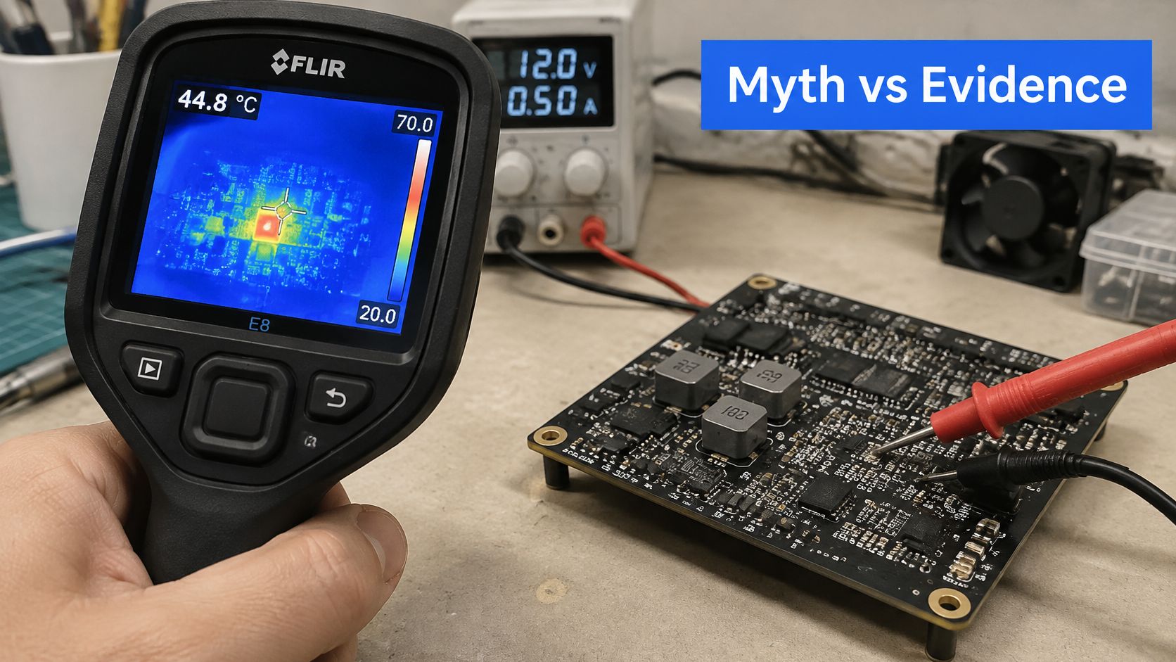
Black mask does not, by itself, make a PCB run meaningfully hotter. Visible-light absorption is not a measure of the heat generated by powered components, and a board's operating temperature depends on its thermal path and surroundings.
On a copper-cooled board, radiation is typically a small share of total heat transfer. Color alone rarely changes operating temperature meaningfully; the effect depends on the enclosure and the board's surface treatment.
<a id="qualify-the-material-and-the-environment"></a>
Qualify the material and the environment
Copper thickness, thermal vias, substrate selection, airflow, and enclosure interfaces are more direct thermal design factors than mask color. If a power device overheats, improve its thermal path rather than relying on a color change.
Reliability depends on the mask formulation and its application. Poor coverage, inadequate curing, or residual contamination can contribute to electrochemical migration. Filler chemistry, surface roughness, wettability, and condensation conditions also affect how moisture and ions interact with the board surface.
For demanding products, qualify the resin system and manufacturing process, not just the color. A properly cured coating with adequate coverage is a different reliability proposition from one applied poorly, even if both are black.
- Material qualification: Require evidence that the actual mask system meets the applicable IPC-SM-840 qualification.
- Application checks: Review adhesion, cure, coverage, and mask condition around conductor edges.
- Environmental testing: Set humidity-bias or insulation-resistance tests to suit the product's voltage, spacing, contamination exposure, and condensation risk.
- Change control: Define which formulation or process changes require renewed approval.
Reliability judgment: Approve the mask system and its application process, not a color name on a quotation.
For thermal-camera comparisons, control measurement conditions and emissivity settings. Otherwise, a difference in apparent surface temperature may reflect how the camera reads the surface rather than a change in component temperature.
<a id="inspecting-assembling-and-designing-black-boards"></a>
Inspecting, Assembling and Designing Black Boards
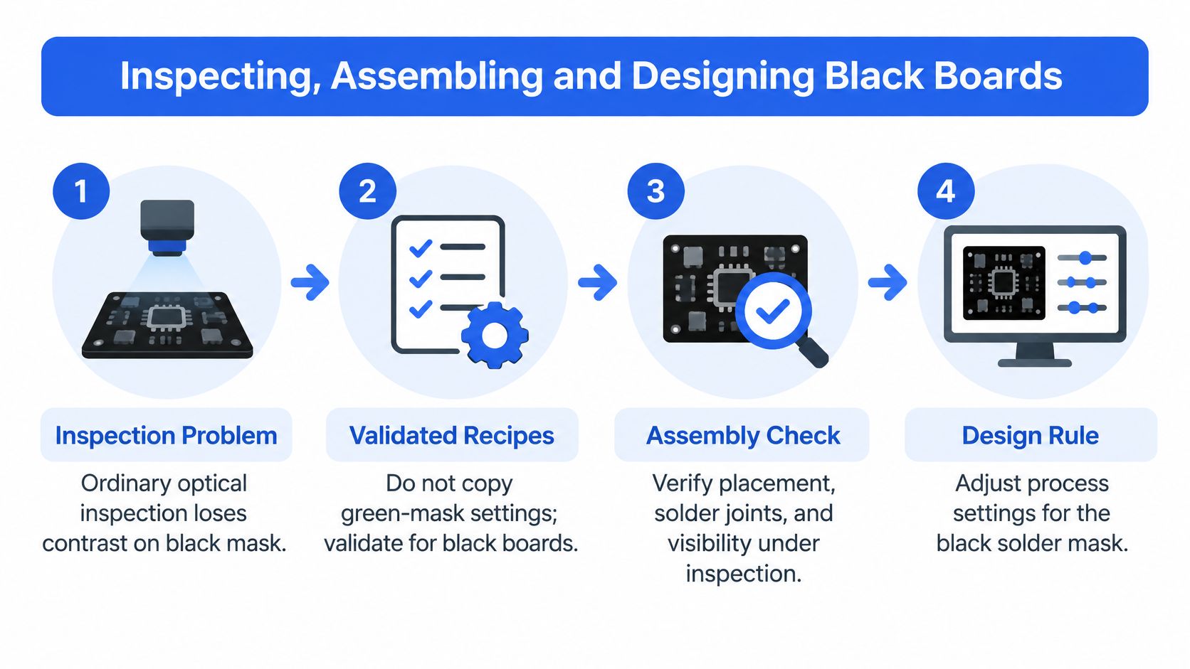
Ordinary optical inspection can lose useful contrast on black mask. The answer is a validated inspection recipe, not an automatic rejection of the finish and not a copied green-board program.
<a id="inspect-in-manufacturing-order"></a>
Inspect in manufacturing order
Start with solder paste inspection before reflow. Check deposited volume, position, and offset while the paste is still measurable independently of the finished joint. This is particularly valuable where fine-pitch printing errors would otherwise become difficult solder-joint investigations.
After placement and reflow, tune automated optical inspection, or AOI, around the defects that matter. Coaxial illumination can provide a baseline, while polarized-coaxial, angled, or scattering light can reveal features that disappear under a single lighting arrangement.
A PCB optical-system study combined different illumination configurations with monochrome and color cameras, reporting contrast of at least 30 gray levels for several defect classes and detection rates of 99.4% for missing components, 88.9% for component damage, and 88.0% for surface scratches. Those are results for the studied system, not promised detection rates for an arbitrary black-board production line.
Use color imaging where color differences help classification and 3D AOI where height information helps distinguish placement or joint conditions. Hidden BGA and QFN connections need an X-ray strategy because optical cameras can't see through the package. Finish with electrical verification appropriate to the bare board and assembled circuit.
Inspection methods and what they catch on black mask
| Method | Strength on black mask | Best use | |---|---|---| | Standard AOI with coaxial light | Reduced contrast, weaker on pinholes | Baseline only; validate the recipe first | | Polarized or angled AOI lighting | Better edge and scratch visibility | Fine-pitch and scratch-prone boards | | Color or 3D AOI | Color cues or height information, respectively | Dense, mixed-height assemblies | | Solder paste inspection before reflow | Paste volume and offset | Fine-pitch boards, before joints form | | X-ray | Hidden BGA and QFN joints, independent of mask color | Any board with BGA or QFN | | Flying-probe or electrical test | Opens, shorts, and continuity | Every board, using the appropriate test stage |
These methods complement one another. Electrical continuity doesn't establish cosmetic acceptability, and a clean AOI result doesn't prove that a hidden joint is sound.
<a id="prepare-the-design-files-for-inspection"></a>
Prepare the design files for inspection
Work through the release package in layout order:
- Set fabrication rules first. Obtain written mask-dam and opening-clearance limits for the selected process.
- Review fine-pitch footprints. Increase pad-to-pad spacing where the footprint and component requirements permit. Don't alter land patterns blindly to preserve a cosmetic mask web.
- Preserve test access. Keep test points exposed, identifiable, and reachable by the planned fixture or probes.
- Protect machine references. Keep fiducials clear and silkscreen legible, without printing over pads or tentatively covered vias.
- Complete the drawing. State color, gloss or matte appearance, and copper weight.
- Release the inspection requirements. Include defect acceptance, hidden-joint inspection, electrical checks, and any board-edge appearance requirement.
Tie those files to the PCB assembly board requirements, rather than leaving inspection assumptions in an email thread. At Lianyuhong, every board is manufactured to IPC-2 or IPC-3 standards with 100% AOI, flying-probe, and electrical testing. We also perform thorough incoming material inspection and AOI, X-ray, and flying-probe testing on every PCB.
<a id="validate-defects-before-production"></a>
Validate defects before production
Suppose a dense BGA design changes to black after layout approval. The assembler must reassess visibility and the AOI program; purchasing shouldn't treat the change as an artwork-only substitution.
Build a sample set containing known mask-registration errors, pinholes, scratches, contamination, exposed copper, and relevant assembly defects. Use the exact mask formulation and finish intended for production, and check both missed defects and false rejects.
Approve mask touch-ups against that sample set and rerun the relevant inspection after rework. Fix the color before layout freeze whenever possible, then validate the recipe before releasing production quantities.
<a id="deciding-whether-to-specify-a-black-board"></a>
Deciding Whether to Specify a Black Board
Specify black when the product benefits from the appearance and the manufacturing plan supports it. Don't pay for it merely to imply quality, and don't reject it merely because a green-board process would be easier to run.
When to specify black solder mask
| Product situation | Recommended mask | Reason | |---|---|---| | Visible consumer or branded product | Black | Appearance is part of what is sold | | First prototype with fine-pitch BGA | Green until yield is understood | Better starting point for first-pass yield and inspection | | High-voltage or humid environment | Black only after humidity-bias testing | Qualification drives reliability | | Metal-core LED or power board | Either, decided by thermal and inspection plan | Color is cosmetic; heat paths matter more |
For an early engineering prototype, prioritize learning about the circuit and assembly process. If black is a firm product requirement, however, don't postpone it until the final production order. Include it in a build early enough to validate manufacturability and inspection before commercial commitments.
Buyers should weigh the quoted board premium against inspection effort, acceptable cosmetic variation, rework responsibility, and delivery risk. A slightly cheaper unit price isn't useful if the acceptance agreement leaves the team arguing over scratches or mask coverage after delivery.
<a id="make-the-release-decision-actionable"></a>
Make the release decision actionable
- Confirm what the customer sees. Review the assembled enclosure, including board edges, connector openings, and display apertures.
- Request a black-mask DFM review. Put approved dam and clearance values into the controlled manufacturing documentation.
- Compare equivalent quotations. Hold construction and acceptance requirements constant when comparing black and green.
- Agree on validation samples. Define the defect set and inspection approval process before the production run.
Choose a PCBA manufacturer whose fabrication and assembly responsibilities match that release plan. Our turnkey PCB assembly includes bare-board fabrication, component sourcing, and full assembly under one roof, with one quality system and one point of accountability. Full-turnkey SMT, THT, and mixed assembly supports fine-pitch and BGA work, from 01005 components to BGA/QFN packages, with AOI, X-ray, and FCT testing.
The decision isn't black versus engineering discipline. Black is a deliberate finish choice, made early and validated against the product's real requirements.
Lianyuhong Technology Co.,Ltd offers PCB fabrication and turnkey assembly to coordinate your black-mask finish with construction, component sourcing, and assembly requirements. Visit Lianyuhong Technology Co.,Ltd with your fabrication files, BOM, and appearance requirements to request a DFM review and a like-for-like quotation for black and green solder mask.