
The most popular advice for choosing a flexible PCB manufacturer is to compare minimum trace width, layer count, and price. That's a useful purchasing exercise, but it won't tell you whether the circuit will survive inside your product. A supplier can meet the fabrication drawing and still deliver a flex assembly that fails when the enclosure forces it through the wrong motion.
Start with a harder question: What exactly was tested? Bend-life claims aren't comparable until the stack-up, fixture, motion, environment, and electrical failure criteria match. A credible shortlist comes from documented manufacturing limits and a production-representative sample, not the largest cycle count on a capability page.
Table of Contents
- Capability Benchmarks to Compare Before You Shortlist
- Setting Bend Radius from the Finished Stack
- Copper and Coverlay Choices by Bend Duty
- Reading Bend-Life Claims Without Being Misled
- Matching Supplier Type to Prototype and Volume Stages
- Verify Quality and Prove the Build with a Sample
<a id="capability-benchmarks-to-compare-before-you-shortlist"></a>
Capability Benchmarks to Compare Before You Shortlist
Flexible PCB capability benchmarks by build type
| Capability | Single/double-sided flex | Multilayer flex | Rigid-flex | What to request | |---|---|---|---|---| | Layer count | Single or double conductive layers | Supplier-declared multilayer stack | Rigid and flex layers combined | Maximum layers per build | | Minimum trace and space | Qualified etched geometry | Qualified geometry by copper layer | Separate rigid and flex limits | Smallest tested geometry, not catalogue minimum | | Bend radius guideline | Finished-stack-based radius | Construction-specific radius | Set by flex-zone thickness | Written radius for your stroke and motion | | Copper type | Electrodeposited or rolled-annealed | Rolled-annealed for dynamic use | Rolled-annealed in moving flex zones | Copper type and thickness for each layer | | Impedance control | Written, measurable tolerance | Written, measurable tolerance | Separate controlled structures by region | Documented stack-up with stated tolerance |
Ask suppliers to complete this table against your fabrication package, not their general capability sheet. An unanswered cell identifies an engineering issue to resolve before purchasing starts negotiating.
Layer count tells you whether a shop can accommodate the routing architecture. It doesn't establish whether the moving section will be sufficiently compliant, whether buried connections are practical, or whether the shop can hold registration across the intended construction. For rigid-flex, request a layer map showing which layers continue through each flex region.
Minimum trace and space must come with copper thickness, location, and inspection evidence. A demonstration panel with an isolated fine line isn't equivalent to a densely routed production panel. Ask whether the quoted geometry is a routine process limit or an exception requiring special review, and request yield evidence for a comparable construction.
<a id="compare-the-manufactured-result"></a>
Compare the manufactured result
Treat mechanical capability as a separate gate. The supplier should identify the finished moving-section thickness, its tolerance, and the proposed bend qualification. A shop that accepts the layer count but can't explain the mechanical stack hasn't finished reviewing the design.
For copper, record both the starting foil and the finished conductor thickness. For coverlay and stiffeners, request material identification, adhesive construction, placement tolerances, and a drawing of the transition boundaries. Connector support and bend freedom often compete for the same small area.
Impedance capability requires a proposed structure, dielectric thicknesses, reference conductors, and an acceptance method. Don't accept an impedance-control checkbox without a stack-up that explains what will be manufactured.
Send every candidate these questions:
- Exact construction: Can you quote my exact stack-up, including coverlay, adhesives, and stiffeners?
- Tested geometry: What's the smallest comparable geometry you've built and electrically tested?
- Documented capability: Where are those limits recorded, and what evidence will accompany my order?
<a id="setting-bend-radius-from-the-finished-stack"></a>
Setting Bend Radius from the Finished Stack
Designing the bend from the enclosure first is a common mistake. The available gap tells you where the circuit must fit, but it doesn't establish how tightly the manufactured circuit can bend. Freeze the proposed flex construction before approving the mechanical path.
The measurement that matters is the finished moving section, including its protective layers.
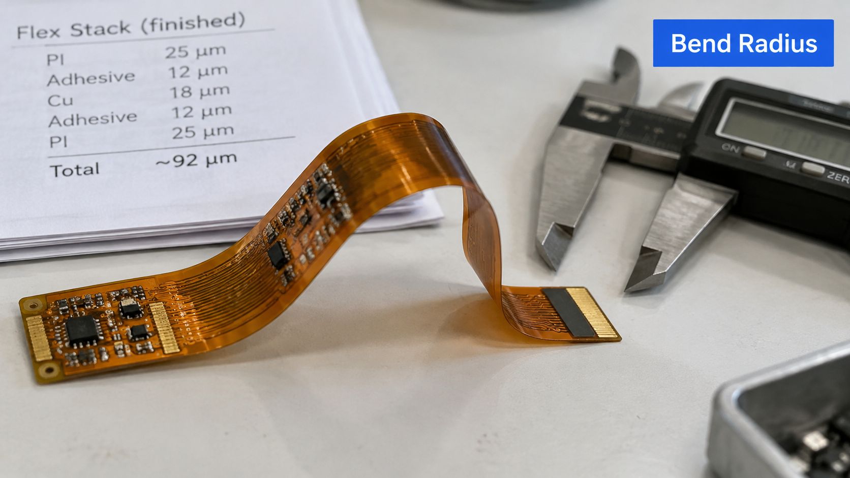
A conservative starting point is approximately 10 times finished thickness for single- and double-sided flex, and 20 times for multilayer flex, with IPC flex-endurance technical work also identifying the importance of production construction and the effective radius during motion. These are screening guidelines, not a guaranteed dynamic-life specification.
When the circuit bends, the outer copper stretches in tension while the inner surface compresses. Thicker copper and a tighter radius increase strain. Adding protective or bonding layers can therefore change mechanical behavior even when the copper artwork remains unchanged.
Practical rule: Approve the radius against the finished flex stack, not the nominal base-film thickness.
<a id="separate-installation-from-continuous-motion"></a>
Separate installation from continuous motion
An installation bend is formed into position and then supported. A wearable strap, display ribbon, or moving hinge experiences a changing path, often with shifting contact points. During movement, the local radius can become tighter than the radius visible in a static enclosure drawing.
Ask the mechanical engineer to review the entire travel envelope, including tolerance extremes, cable tension, and possible rubbing. For rigid-flex transitions, use the same drawing discipline described in these rigid-flex PCB design guidelines, especially where a supported region becomes free to move.
Apply the design controls in this order:
- Define the neutral flex zone. Mark the intended moving span and its support boundaries.
- Remove local stress concentrators. Keep plated holes and sharp trace corners outside the highest-strain region.
- Distribute conductors. Stagger routing where practical rather than concentrating stiffness along a single line.
- Qualify the construction. Use production-representative samples and an agreed IPC-TM-650 flex-endurance procedure.
Use the video alongside the mechanical drawing review, not as a substitute for a written test specification.
<iframe width="100%" style="aspect-ratio: 16 / 9;" src="https://www.youtube.com/embed/IZ1QB_HsMhk" frameborder="0" allow="autoplay; encrypted-media" allowfullscreen></iframe>Put this sentence into the specification and complete every field: The finished flex-stack thickness and tolerance shall be [value]; the minimum permitted radius shall be [value] throughout a stroke of [value], at a speed of [value], over an operating temperature range of [value].
<a id="copper-and-coverlay-choices-by-bend-duty"></a>
Copper and Coverlay Choices by Bend Duty
Material sets by bend duty
| Duty | Copper | Base construction | Coverlay | |---|---|---|---| | One-time installation bend | Electrodeposited copper acceptable after mechanical review | Adhesive polyimide acceptable | Standard coverlay qualified for forming | | Continuous dynamic flex | Rolled-annealed copper | Adhesiveless polyimide preferred | Thin coverlay over the flex zone | | Wearable hinge or strap | Thin rolled-annealed copper | Adhesiveless polyimide preferred | Thin coverlay, no plated holes in the flex area | | Dynamic flex with high-temperature assembly | Rolled-annealed copper qualified after assembly | Polyimide base, confirm thermal compatibility | Thin polyimide coverlay with assembly-compatible adhesive |
These are starting material selections, not interchangeable recipes. A circuit that only folds during installation can justify a different cost and construction balance from one that moves throughout service. Don't pay for a dynamic material set without understanding the duty, but don't substitute a static construction because the prototype bent successfully by hand.
IPC-published copper and coverlay reliability work describes a comparison in which polyimide inclusion improved endurance from hundreds to thousands of cycles, and supports selecting ductile copper and controlling protective construction. The useful lesson isn't a transferable cycle guarantee. It's that coverlay belongs in the mechanical design, rather than being treated solely as electrical insulation.
Coverlay distributes local stress and protects conductors against handling and environmental damage. It can't rescue an overstrained conductor or a poor transition layout.
<a id="balance-ductility-thickness-and-assembly-needs"></a>
Balance ductility, thickness, and assembly needs
Rolled-annealed copper is generally preferable for repeated bending because its elongated grain structure provides greater ductility than electrodeposited copper. Thinner copper reduces strain at a given radius, but it also constrains current capacity and may require wider conductors. Resolve that trade-off electrically and mechanically before releasing artwork.
Adhesiveless polyimide removes the base bonding layer from the construction. It doesn't mean the completed circuit contains no adhesive, because the coverlay and local reinforcements may still use it. Ask for a cross-sectional material schedule rather than accepting adhesiveless as a complete stack description.
A thinner coverlay can help preserve flexibility, but pad openings, insulation requirements, handling resistance, and lamination quality still need review. For assemblies exposed to demanding soldering conditions, qualify the flex after the intended assembly process, not just as an unassembled board.
Watch the layout details that can override material selection:
- Width changes: Taper transitions rather than introducing abrupt conductor steps near the moving span.
- Via support: Keep unsupported vias out of mechanically active transitions.
- Conductor grouping: Avoid dense bundles that create a sudden stiffness change at the bend entrance.
Send a controlled material schedule specifying copper type, finished copper thickness, base construction, coverlay thickness, and target cycle count. Include material-compliance documentation in the purchasing package; we are a UL recognized PCB manufacturer and use RoHS and REACH compliant materials.
<a id="reading-bend-life-claims-without-being-misled"></a>
Reading Bend-Life Claims Without Being Misled
A supplier may advertise high bend endurance without telling you whether the test involved gentle rolling, repeated sharp folding, or a completed assembly. That claim isn't necessarily false. It isn't a purchasing specification.
JLCPCB's flex-fabrication discussion illustrates the comparison problem: dynamic-bend guidance can range from roughly 10–15 times total thickness to 100 times or more, while reported endurance includes approximately 100,000 cycles for rolled-annealed copper versus 10,000 for electrodeposited copper, and severe folding comparisons of 200–500+ versus 10–50 cycles, respectively. Those figures describe different conditions, not competing guarantees for your product.
Reported endurance figures and how to read them
| Reported figure | Copper and base | Test definition | How to read it | |---|---|---|---| | Higher cycle count in the industry comparison | Rolled-annealed copper; base must be confirmed | Radius and speed must be obtained | Confirm the complete fixture and motion definition | | Lower cycle count in the same comparison | Electrodeposited copper; base must be confirmed | Matching conditions must be established | Compare only after checking construction | | Higher folding endurance in the severe test | Rolled-annealed copper, adhesiveless polyimide | Severe folding method | Not a dynamic-bend specification | | Lower folding endurance in the severe test | Electrodeposited copper | Severe folding method | Confirm whether bare FPC or assembled PCBA was tested |
<a id="force-the-test-definition-into-the-quotation"></a>
Force the test definition into the quotation
Ask these questions in writing, and require the answers to accompany any endurance claim:
- Duty classification: Is the circuit static, installation-bend, or continuously dynamic? What constitutes a complete cycle?
- Mechanical and electrical conditions: What bend axis, angle, radius, speed, temperature, tension, and electrical failure limit were used?
- Tested article: Does the result apply to bare FPC or assembled PCBA, including stiffeners, connectors, solder joints, and adhesive zones?
- Monitoring method: Was continuity monitored during movement, or only checked after cycling stopped?
The distinction between continuous monitoring and a final electrical check matters. A brief intermittent open during motion can be unacceptable even if the circuit conducts again when the fixture returns to rest.

A bend-life result belongs to the tested construction and test method. It doesn't automatically belong to every board made from the same copper.
A useful report identifies the specimen drawing revision, material schedule, fixture geometry, environmental conditions, monitoring setup, and failure definition. It should distinguish completed tests from tests stopped without failure.
Request a coupon that reproduces your routing, radius, motion profile, and environment. If the supplier proposes a simpler coupon, require an explanation of what it represents and what it leaves unqualified. A generic test strip can characterize a material process, but it can't prove connector retention or assembled-product behavior.
<a id="matching-supplier-type-to-prototype-and-volume-stages"></a>
Matching Supplier Type to Prototype and Volume Stages
Supplier fit by production stage
| Stage | Typical quantity | Priority | Documentation to request | |---|---|---|---| | Prototype | Enough to evaluate fit and function | Fast turn and DFM feedback | Fabrication drawing and stack-up | | Pilot run | Enough to exercise the intended production process | Stable yield on the same stack-up | Process capability data | | Low-volume production | Scheduled batches matched to demand | Repeatable assembly and component sourcing | Traceability records and first-article report | | Volume ramp | Capacity-backed recurring orders | Capacity, second source, and change control | Quality system certificate and change notice process |
Use process maturity, not an arbitrary board count, to define the stage. A small regulated build may need stronger documentation than a much larger consumer prototype order. Quantity alone doesn't tell you which supplier is suitable.
A prototype-focused shop earns its place by returning useful DFM feedback and making engineering changes manageable. That flexibility becomes a liability if operators substitute materials, tooling, or inspection methods without recording the change. Before a pilot run, lock the construction and establish which process steps will remain unchanged.
<a id="choose-for-the-next-production-gate"></a>
Choose for the next production gate
At pilot stage, ask how the supplier separates fabrication losses from assembly losses. A single overall yield statement can conceal whether the problem is etched geometry, lamination, handling, solder printing, or component placement. You need defect categories that your engineers can act on.
For recurring production, evaluate component purchasing, assembly fixtures, lot segregation, and responsibility for nonconforming boards. If bare-board fabrication and assembly sit with different organizations, define who investigates a failure at the interface. These PCBA manufacturer selection criteria help frame the broader assembly review.
Asia-Pacific's concentrated FPCB manufacturing ecosystem, described in Mordor Intelligence's market analysis, can simplify access to fabrication and component supply, but buyers still need explicit allowances for time-zone handoffs, shipping, and customs.
A prototype partner becomes the wrong partner when it can't support the documentation, qualification, or sourcing controls required by the next product release. Automotive and medical programs need more than an assurance that the shop has built similar boards.
Sourcing decision: Choose the supplier whose records support your next production stage, not merely the supplier with the cheapest first build.
Before a capacity commitment, agree how an alternate source would reproduce the approved construction. Material availability, transferable tooling information, and controlled drawings matter more than a vague promise of backup capacity.
<a id="verify-quality-and-prove-the-build-with-a-sample"></a>
Verify Quality and Prove the Build with a Sample
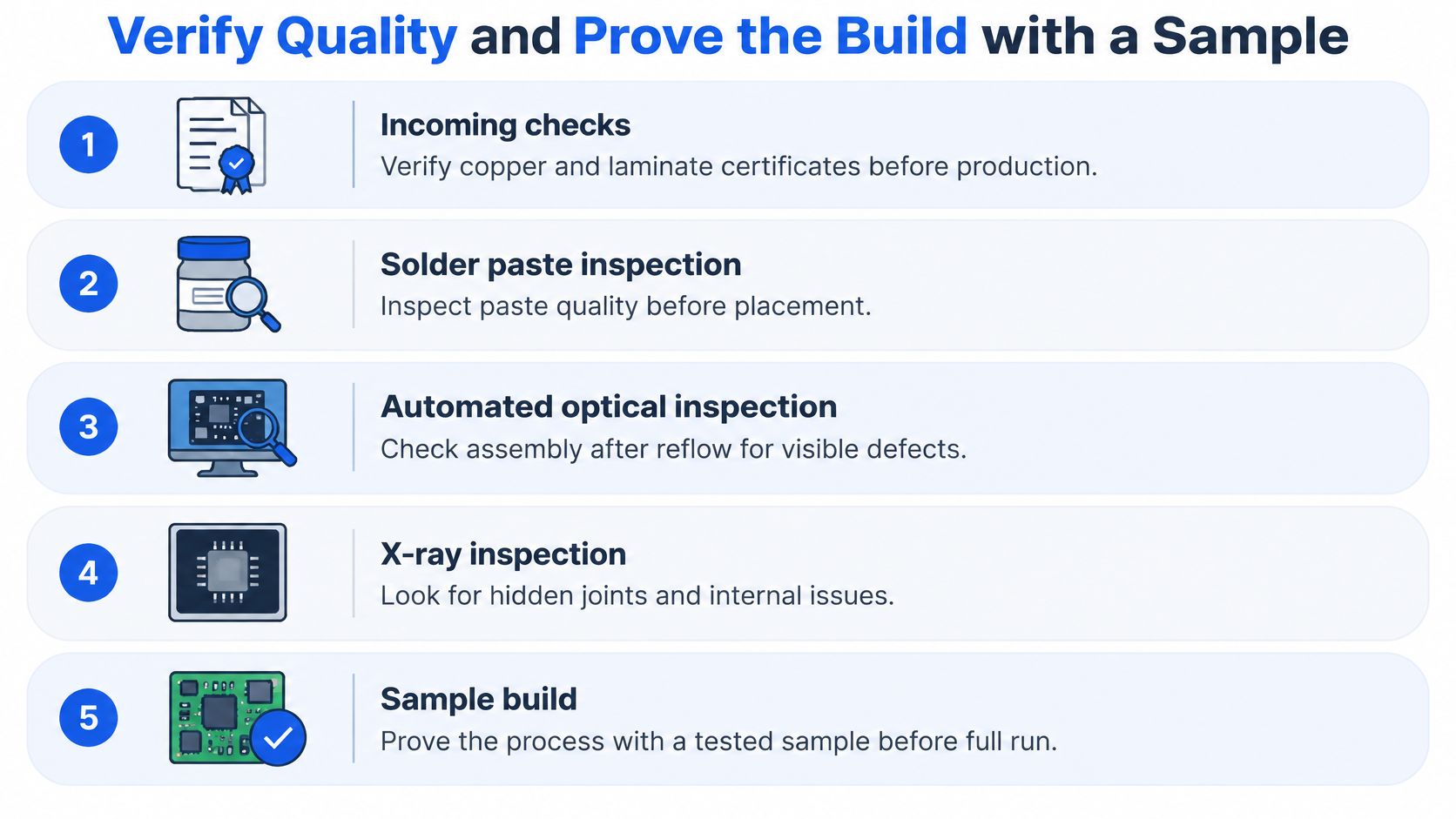
Review the inspection chain in process order, while distinguishing bare-board fabrication from assembly. Incoming checks should reconcile copper and laminate certificates with the approved material schedule. During assembly, solder paste inspection checks deposits before placement, automated optical inspection checks visible conditions after reflow, and X-ray examines hidden joints beneath BGA and QFN packages.
Flying-probe testing belongs to bare-board electrical acceptance before assembly, even if a supplier lists it alongside assembly inspections. It checks accessible nets for continuity and isolation; it doesn't establish dynamic life. Functional testing must exercise the intended electrical behavior, with motion included where movement can affect operation.
Request microsection cross-sections to inspect plating and relevant laminated interfaces, including coverlay where appropriate. For controlled-impedance builds, require coupon results against the agreed structure and tolerance. Neither a passing coupon nor a clean X-ray replaces the other inspections.
<a id="check-scope-and-traceability"></a>
Check scope and traceability
A serial or lot identifier should connect a delivered assembly to its material lots, fabrication revision, assembly records, inspections, and disposition of nonconformances. Test that connection by selecting a sample and asking for its manufacturing history. A traceability policy isn't enough if the records can't be retrieved.
Certification also needs scope. Review IATF 16949 for the relevant automotive manufacturing operation, ISO 13485 for regulated medical builds, and the specified IPC-6013 acceptance class for the flex board itself. Use the applicable PCB design standards to align the drawing and inspection requirements.
Our PCB fabrication is IATF 16949 certified, qualifying us as a turnkey PCBA supplier for automotive electronics. We also offer medical PCB assembly under an ISO 13485 quality system for regulated turnkey medical builds. Those credentials don't replace application-specific qualification.
Our polyimide-based offering covers FPC with 1–8 layers, rigid-flex with 2–14 layers, and 0.04 mm minimum trace for compact, dynamic applications; our turnkey service includes bare-board fabrication, component sourcing, and full assembly under one roof with one quality system and one point of accountability. Treat those capabilities as inputs to a design review, not automatic approval of a particular moving assembly.
<a id="run-a-controlled-sample-release"></a>
Run a controlled sample release
- Submit the mechanical and electrical package. Include stack-up, minimum radius, motion profile, temperature range, and target life.
- Close the DFM review in writing. Record each accepted change and update the released drawing rather than relying on email interpretation.
- Build production-representative samples. Use the intended materials, tooling approach, assembly process, and inspection route.
- Execute the endurance protocol. Monitor continuity during cycling and retain the failure-limit settings and results.
- Audit the evidence. Match sample identifiers to material certificates, inspection records, electrical results, and any deviations.
- Agree change control. Define which substitutions or process changes require notification, approval, or requalification before production purchasing.
Shortlist only manufacturers that pass the same sample protocol and return usable records. If a supplier can't reproduce the qualification construction, its successful sample isn't a reliable basis for the production order.
Lianyuhong Technology Co.,Ltd offers polyimide flexible and rigid-flex PCB fabrication with turnkey component sourcing and assembly. Visit Lianyuhong Technology Co.,Ltd with your stack-up, bend envelope, motion profile, and acceptance requirements to discuss a DFM review and production-representative sample build.