
The usual advice on surface mount vs through hole is incomplete: choose SMT for size and cost, choose through-hole for reliability. That shortcut confuses the strength of a component attachment with the reliability of the entire board. A connector's load path, a buried via's geometry, or the setup burden of a small production run can change the decision. Choose the assembly method by the failure you need to prevent and the production stage you're funding.
Table of Contents
- Surface Mount and Through Hole at a Glance
- Mechanical Strength Where Parts Take Load
- Thermal Cycling and Where Joints Actually Fail
- Cost and Volume Breakpoints for Each Method
- Mixing Both Methods on One Board
- Which Method Fits Your Product Situation
- Confirm the Assembly Method Before Your Next Board Order
<a id="surface-mount-and-through-hole-at-a-glance"></a>
Surface Mount and Through Hole at a Glance
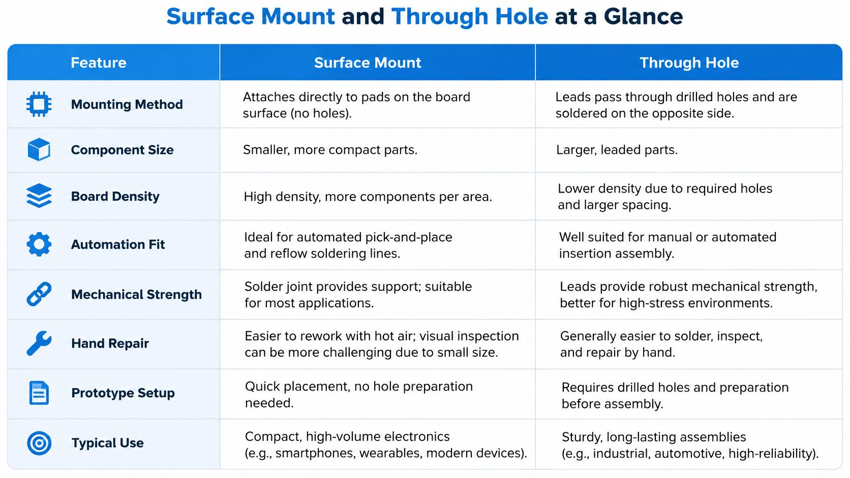
| Criterion | Surface mount (SMT) | Through hole (THT) | |---|---|---| | Mounting | Pads on the board surface | Leads pass through drilled holes and are soldered on the far side | | Component size | Small packages, including fine-pitch BGA and QFN | Larger bodies, often connectors, transformers, and bulk capacitors | | Board density | High, with placement on both sides | Lower routing flexibility because holes occupy space through the board | | Automation fit | Pick-and-place followed by reflow | Manual or automated insertion, followed by wave, selective, or hand soldering | | Mechanical strength | Loads pass through pad adhesion and solder fillets | Leads and plated barrels provide mechanical anchoring | | Hand repair | Fine-pitch and hidden joints need specialized rework tools | Accessible leads can be repaired with an iron and desoldering tool | | Prototype setup | Production reflow usually requires a stencil and placement program | Hand insertion can start without a stencil | | Typical use | Phones, IoT devices, compact controllers | Connectors, power parts, and mechanically stressed locations |
Market share establishes which method dominates production, not which will survive your application. Surface-mount devices accounted for approximately 75% of global electronic-components market revenue in 2024, according to Market Research Future. Separately, SMT accounted for 66.47% of global PCB assembly market revenue in 2025, according to Mordor Intelligence.
SMT components sit on pads on the board surface, as described in the surface-mount technology overview. THT component leads pass through drilled holes and are soldered on the opposite side.
The comparison below summarizes those physical and manufacturing differences.
<a id="choose-by-constraint-not-popularity"></a>
Choose by constraint, not popularity
The mounting difference affects much more than component appearance. A leaded footprint reserves drilling and routing space, while an SMT footprint puts greater emphasis on paste deposition, placement, and surface-pad design. Neither process removes the need to plan inspection and repair.
Through-hole remains useful where large component bodies, connector retention, transformer construction, or serviceability determine the package choice. Replacing such a part with an SMT equivalent is worthwhile only if the revised design still meets its mechanical and maintenance requirements.
For a compact product intended for automated production, SMT is a sensible starting point. Retain THT selectively when the component's physical role justifies it, rather than converting the whole board to match a preferred assembly label.
Copy the table into your design review and add a priority column. Mark the criteria your product cannot compromise, such as enclosure size, field replacement, or cable retention, before comparing footprints.
<a id="mechanical-strength-where-parts-take-load"></a>
Mechanical Strength Where Parts Take Load
| Joint type | Reported shear strength | Load path | |---|---|---| | SMT rigid lap joint | Approximately 3.48–8.70 psi | Pad adhesion and solder fillet | | SMT LCC termination | Approximately 4.64–9.28 psi | Pad adhesion and solder fillet | | SMT gull-wing lead | Approximately 3.48–5.80 psi | Pad adhesion and solder fillet | | Through-hole lead | No comparable value stated | Plated barrel, solder meniscus, and component lead |
The representative SMT ranges in the EPTAC solder-joint reference are approximately 3.48–8.70 psi for rigid lap joints, 4.64–9.28 psi for LCC terminations, and 3.48–5.80 psi for gull-wing leads. Geometry, board finish, solder alloy, and test method affect these values, so they aren't component-level acceptance limits or a basis for calculating a universal THT strength advantage.
The useful distinction is the load path. An SMT component transfers force through its terminations, solder, and surface pads; a through-hole attachment distributes force through the lead, solder meniscus, and plated barrel. Under cable pull or repeated insertion, that difference can matter more than the component's electrical function.
<a id="identify-the-parts-that-carry-external-force"></a>
Identify the parts that carry external force
Review these parts before releasing the layout:
- Connectors and switches: Trace insertion, extraction, and operating forces into the PCB or enclosure.
- Transformers and relays: Consider component mass, vibration, and whether the body needs additional restraint.
- Large electrolytic capacitors: Check how the assembly supports the body during shock and board movement.
- User-accessible interfaces: Treat anything a person plugs in, pulls, presses, or flexes as a mechanical design item.
A through-hole package isn't the only solution. A mechanically secured SMT connector may be appropriate when enclosure features or mounting hardware carry the external force. What matters is whether the solder joints are electrical connections or unintended structural fasteners.
Practical rule: Don't treat a larger SMT solder fillet as a substitute for a designed retention feature.
Validate pull, shear, vibration, and board-bending performance using the actual package and laminate stack-up. Inspect both the joint and the board afterward; a sound-looking solder fillet doesn't establish that the pad or laminate remained intact.
For the next mechanical review, label each relevant BOM item with its load type: insertion, cable pull, vibration, or none. Flag every externally loaded part for a documented retention decision.
<a id="thermal-cycling-and-where-joints-actually-fail"></a>
Thermal Cycling and Where Joints Actually Fail
SMT is not naturally less reliable under thermal cycling. Joint geometry, package compliance, lead length, pad design, material expansion mismatch, and temperature profile determine how strain reaches the solder.
A mixed board makes the range of attachment geometries visible.
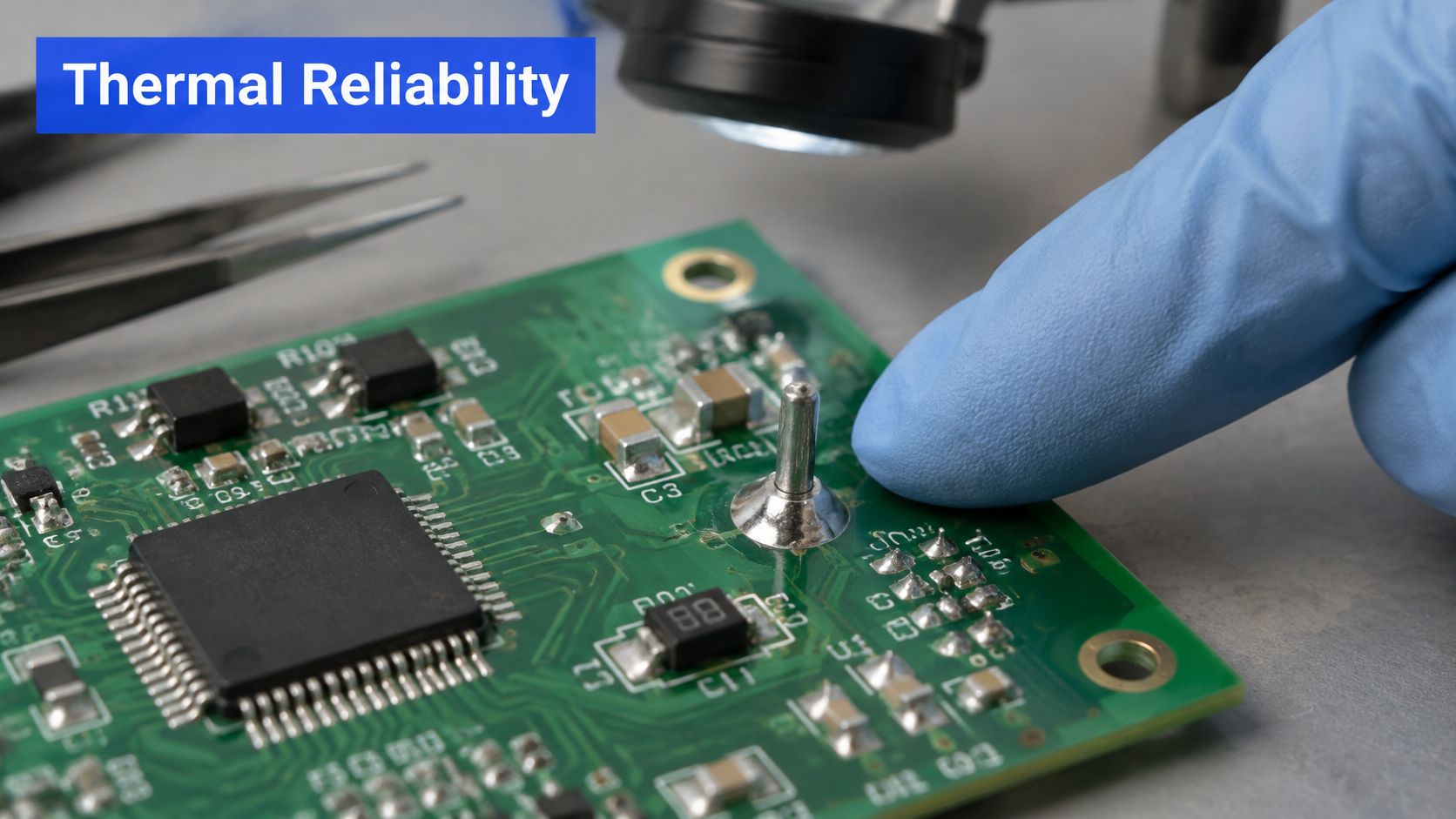
Dissimilar materials expand at different rates. Repeated temperature changes impose cyclic shear, which can cause solder plasticity, creep, and fatigue, particularly in constrained leadless packages. A compliant lead and a rigid termination therefore shouldn't be treated as equivalent merely because both belong to the same assembly category.
The European Space Agency reliability guidance cites example qualification requirements of 500 thermal cycles from -55°C to 100°C for SMT assemblies, versus 200 cycles for THT assemblies. Those are qualification examples, not matched service-life results demonstrating that either technology lasts longer.
<a id="control-the-geometry-and-the-process"></a>
Control the geometry and the process
For leadless SMT and large-area packages, review pad geometry, solder volume, and thermal-fatigue behavior together. For THT, examine barrel fill, lead-to-hole clearance, and stress concentration where the lead enters the board. A package substitution can change the stress distribution even when the circuit remains electrically identical.
Distinguish an assembly defect from damage accumulated in service. A cold solder joint requires a process investigation; a fatigue crack requires investigation of cyclic strain and operating exposure. Reflowing a failed joint without establishing the mechanism doesn't validate the design.
For a visual companion to the assembly discussion, use the following video.
<iframe width="100%" style="aspect-ratio: 16 / 9;" src="https://www.youtube.com/embed/0eDrDeEkUDs" frameborder="0" allow="autoplay; encrypted-media" allowfullscreen></iframe><a id="qualify-the-assembly-you-will-ship"></a>
Qualify the assembly you will ship
The ESA guidance also describes established predictive models for SMT and less mature comparable tools for THT. That makes conservative empirical testing and finite-element assessment useful for through-hole designs, rather than assuming lead anchoring resolves thermal risk.
- Define the exposure: Specify operating extremes, transitions, and dwell conditions before selecting a test profile.
- Monitor continuity: Look for intermittent electrical failures, not just visible damage.
- Cross-section suspect locations: Examine solder interfaces and plated structures to identify where failure began.
For harsh thermal service, use accelerated cycling and cross-section analysis on representative assemblies. Select the method that passes the relevant qualification, not the one with the stronger reputation.
<a id="cost-and-volume-breakpoints-for-each-method"></a>
Cost and Volume Breakpoints for Each Method
| Cost driver | Surface mount | Through hole | |---|---|---| | Setup per design | Stencil, feeder setup, placement program | Insertion tooling and wave or selective solder pallet when required | | Placement labor per board | Low at volume with automated placement | Higher when insertion is manual | | Inspection | AOI, with X-ray for hidden joints | Accessible-joint inspection plus electrical and functional checks | | Rework | Hot-air or controlled reflow equipment | Desoldering and reinsertion, with barrel protection | | Engineering change | Stencil and program updates when affected | Drill, footprint, and fixture updates when affected |
SMT's placement efficiency doesn't guarantee the lowest prototype cost. Feeder preparation, programming, packaging, stencil procurement, and engineering changes must be paid for before automated placement produces savings. THT can avoid some of that setup, but insertion labor, fixtures, soldering, and inspection still belong in the quote.
EE Times' coverage of PCB assembly automation describes equipment capable of more than 200,000 placements per hour with approximately ±0.025 mm placement accuracy. That's scale context, not a finished-board throughput promise: printing, handling, reflow, inspection, and testing remain part of the route.
<a id="calculate-the-crossover-from-quoted-costs"></a>
Calculate the crossover from quoted costs
Use a stage-specific cost model rather than a universal volume threshold:
- Record demand and revision risk. Separate the immediate build quantity from annual demand and note which engineering changes could invalidate tooling or purchased material.
- Estimate fixed setup and recurring cost for each route. Include insertion, soldering, inspection, expected rework, test access, component purchasing, and freight.
- Model prototype, pilot, and production separately. Don't spread prototype setup over production units that haven't been authorized.
- Compare total landed cost at each planned quantity, then calculate where lower recurring cost repays higher setup.
The calculation is straightforward:
Break-even quantity = additional fixed setup cost ÷ recurring saving per board.
Use this only when the alternatives have equivalent scope and a positive recurring saving. Include any added mixed-assembly process cost rather than comparing SMT placement alone against a complete THT build.
For low-volume PCB assembly, our turnkey service has no minimum order quantity, and prototypes can start with one board. Our SMT stencils start from $5.00 per piece, and PCB assembly starts from $0.008 per joint.
Those are starting prices, not total project estimates. Use a detailed quotation to account for the actual BOM, tooling, inspection, and assembly route before deciding that a small batch should be hand-built.
<a id="mixing-both-methods-on-one-board"></a>
Mixing Both Methods on One Board
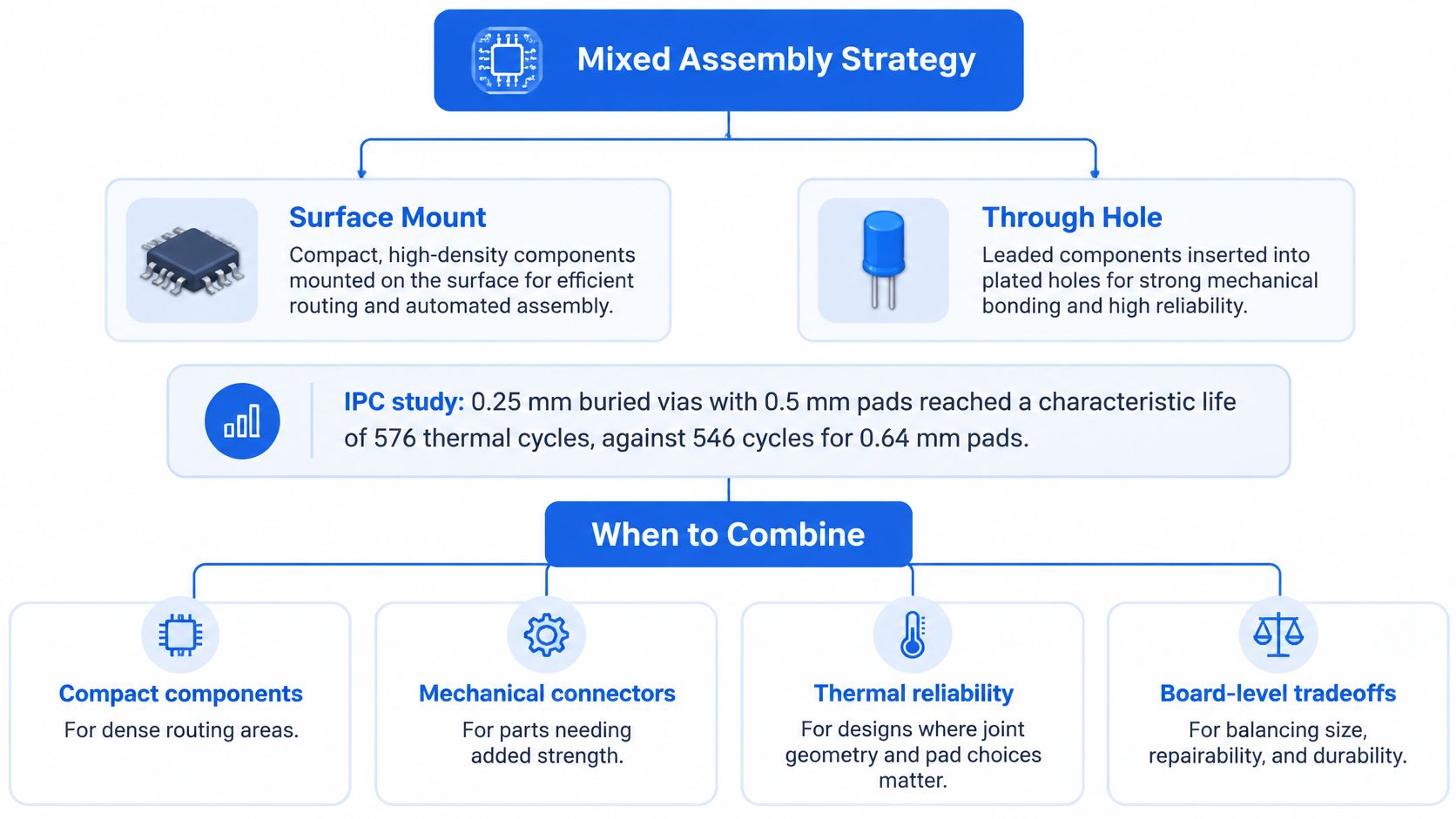
An IPC reliability study of an HDI test vehicle found that 0.25 mm buried vias with 0.5 mm pads reached a characteristic life of 576 thermal cycles, compared with 546 cycles for 0.64 mm pads; with drill offset, the corresponding results were 599 versus 428 cycles. The smaller-pad result challenged the assumption that a complete annular ring always provides greater reliability.
This wasn't an SMT-versus-THT component test. Its importance is that a board-level feature can upset a seemingly safe geometric rule. Selecting strong component attachments won't compensate for an unsuitable via structure, laminate, or fabrication tolerance.
The mixed-assembly strategy below separates component placement needs from board-level reliability decisions.
<a id="combine-methods-only-where-they-solve-a-requirement"></a>
Combine methods only where they solve a requirement
Use SMT for the compact circuitry and reserve THT for locations where mechanical loading, package availability, or maintenance justifies it. This avoids forcing a dense controller into leaded packages because its power connector needs anchoring.
Our turnkey assembly supports FR-4, HDI, flexible, rigid-flex, metal-core, and high-frequency boards, with SMT, through-hole, or mixed assembly on single- and double-sided boards. The substrate decision still needs its own thermal, mechanical, and fabrication review.
A practical process route is SMT placement and reflow, followed by through-hole insertion and wave or selective soldering. Our capabilities include nitrogen reflow, wave and selective soldering, SMT from 01005, BGA from 0.35 mm pitch, and through-hole assembly for connectors and power parts. Fine-pitch and miniature packages warrant close attention to placement and paste control.
<a id="review-the-interaction-between-processes"></a>
Review the interaction between processes
- Soldering access: Preserve room for selective-solder tooling or the required wave-solder protection around nearby SMT parts.
- Thermal exposure: Confirm component temperature ratings against every process the populated board will encounter.
- Inspection coverage: Specify how hidden joints will be inspected rather than relying on visible fillets.
- Board construction: Review buried vias, annular rings, drill offset, and laminate behavior alongside component joints.
A mixed board is justified when each method removes a specific risk, not when the design merely contains familiar packages.
Compare mixed and single-method candidates on the actual stack-up, including assembly yield, repair access, and environmental testing. Adopt the mixed route when those results justify its additional processing.
<a id="which-method-fits-your-product-situation"></a>
Which Method Fits Your Product Situation
| Product situation | Recommended method | Main reason | |---|---|---| | Battery-powered IoT sensor on a small board | SMT only, if interfaces aren't mechanically stressed | Density and low weight | | Handheld device with a plug-in connector | SMT with a through-hole connector or separately anchored interface | Insertion and cable loading | | Mains power supply with a large transformer | Mixed, with THT for transformer and bulk capacitors | Heavy-component support | | LED driver with heatsink-mounted power parts | Mixed where leaded power packages suit the mounting arrangement | Mechanical retention and thermal mounting | | Small prototype batch | Outsourced SMT with hand-fitted THT where practical | Avoid unnecessary tooling while retaining required packages | | Industrial controller with frequent field service | Mixed, with accessible connectors and relays | Repair access and mechanical durability | | High-volume consumer board | Predominantly SMT, with justified mechanical exceptions | Automated assembly and compact packaging |
These recommendations are starting conditions, not package mandates. An LED driver doesn't require THT because it handles power, and a handheld product doesn't automatically require a through-hole connector. The package, enclosure, cooling arrangement, and service plan must agree.
<a id="resolve-competing-requirements-at-the-part-level"></a>
Resolve competing requirements at the part level
For an IoT sensor, the decisive constraint may be enclosure area. If its connections are soldered wires or otherwise restrained, adding leaded packages can consume space without solving a mechanical problem.
A handheld device presents a different question: who carries the cable force? If the enclosure secures the connector, an SMT interface may be viable; if the board attachment carries that force, retention needs explicit validation.
For an industrial controller, define what a technician will replace. Accessible connector and relay joints may support a repair plan, but choosing THT won't help if the enclosure prevents tool access or nearby components obstruct desoldering.
- Board size: Identify footprints that prevent the layout from fitting the enclosure.
- Production route: Match the package selection to the intended assembly and inspection processes.
- Service access: Check the soldering tool's approach and component removal path.
- Mechanical support: Identify whether the PCB, enclosure, bracket, or heatsink carries each load.
<a id="treat-prototypes-as-a-production-stage-of-their-own"></a>
Treat prototypes as a production stage of their own
A small build can combine outsourced SMT with hand-fitted leaded parts. That can be practical when the leaded parts are few and accessible, but it isn't automatically cheaper once engineering labor and rework are counted.
Start with SMT for compact circuitry, then make explicit exceptions for loaded or service-critical parts. Use mixed assembly when those requirements coexist, and avoid changing package technology solely to make the board uniform.
Before selecting the route, tag each BOM item compact, loaded, or service-critical. Allow multiple tags where necessary; those are the parts most likely to need a joint mechanical, layout, and manufacturing decision.
<a id="confirm-the-assembly-method-before-your-next-board-order"></a>
Confirm the Assembly Method Before Your Next Board Order
-
Tag the BOM. Mark compact, loaded, and service-critical components, then identify any package whose mounting requirements remain unresolved.
-
Choose the process by component group. Record why each exception requires THT or additional mechanical retention so purchasing substitutions do not remove that feature unnoticed.
-
Resolve sourcing risks before authorization. During our BOM review, we flag scarce or end-of-life parts and suggest drop-in replacements before you authorize purchasing. Obsolete parts without a direct substitute can be customer-supplied under partial turnkey.
-
Export manufacturing and placement files. We accept Gerber RS-274X, ODB++, and IPC-2581; include the BOM and pick-and-place file so engineers can review both board construction and assembly intent.
-
Request comparable quotations. Where technically feasible, compare SMT-only and mixed routes for prototype and pilot builds, including tooling, testing, lead times, and total landed cost. Use the same acceptance requirements when evaluating a PCBA manufacturer.
-
Confirm process compatibility. Check soldering-tool clearance, component thermal exposure, and inspection coverage before freezing the layout.
Our process begins with secure upload of Gerber, BOM, and pick-and-place files, followed by engineering review for DFM feedback and component availability. You then receive a detailed quotation with pricing and lead-time options before manufacturing, assembly, testing, and worldwide shipment.
Send the BOM and Gerber files for DFM review before committing to an assembly method.
Lianyuhong Technology Co.,Ltd offers turnkey SMT, through-hole, and mixed PCB assembly, including component sourcing and inspection for prototype through production builds. Visit Lianyuhong Technology Co.,Ltd to submit your design files and request a DFM review and quotation based on your board's mechanical, thermal, and production requirements.